Page 32
©2013 Technical Marine Service, Inc. LC-100 V2.97
Pneumatic Connections
General
Pneumatic connections are made at
the bottom of the LevelCom 100
enclosure. The instrument is
supplied with fittings installed as
required by the options ordered.
Connections are 1/8” female NPT. If
it is necessary to install a fitting,
thread lubricant should be used
sparingly, with great care taken to
keep excess from entering the
manifold. Do not use PTFE tape on
any pneumatic connections to the
LevelCom 100. Fittings should be
made up only as tight as necessary
to be leak-free. The manifold is
aluminum, and can be distorted by using excessive installation force. Small fittings, such as
1/8” NPT do not require much torque to seal well. The pneumatic connection ports are
discussed below.
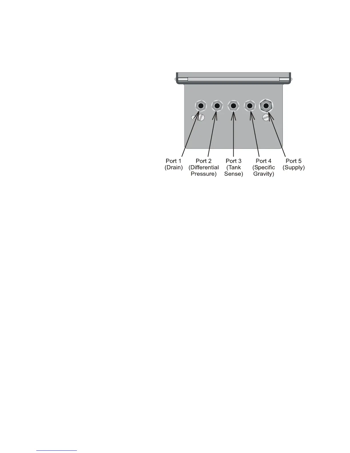
In the majority of cases, tubing connections are made only to Port 3, (Tank Sense) and Port
5, (Supply air). See Figure 18. These will usually be the only fittings present. The others
are only present if the relevant options were ordered.
Note: There is a filter between the compression fitting and the manifold body on the Port 5
the air supply fitting. This filter should not be removed from the manifold body. If different
fittings are required proper fittings should be obtained that will thread onto this filter.
Port 1 DRAIN is used at regular intervals by the LevelCom 100 to purge its manifold of any
water, oil or impurities, and to relieve all pressure to the internal sensor for periodic automatic
zero calibration. If desired, the DRAIN connection may be plumbed to a different location, so
that when the LevelCom 100 vents, the air will be directed elsewhere. Tubing is to be made
up tight and leak free and tubing connections must not obstruct flow or contain any valves.
Important Note: Tubing must be arranged so that the entire run slopes downward to the
open end. If liquid can be trapped in this tubing anywhere the hardware zero operation will
not work correctly and the machine accuracy will be affected. Use of clear plastic tubing is
recommended to aid in seeing possible problems with contaminated air.
Figure 18 Pneumatic Connections