Page 31
©2013 Technical Marine Service, Inc. LC-100 V2.97
Note: For information on connections at the computer’s serial port, refer to the manual
supplied with the computer. There is not one standard pinout for RS-422/485 connections.
See Appendix A for wiring diagrams for 3 wire and 5 wire RS-422/485 systems.
Digital Communication
A LevelCom 101 may be used as a
remote readout for the LevelCom 100.
This function will use the Digital
Communication option. This requires the
Digital Communication option board to be
installed. This board is installed in the
place of the analog output module on the
Sensor Input Circuit Board. The Digital
Communication module uses the same
output connector as the Analog Output
Module.
Important note: The jumpers on the
Sensor Input Circuit Board must be set for
External. Refer to Figure 15 and Figure
16 for the correct jumper settings
depending on the version of the Sensor Input Circuit Board.
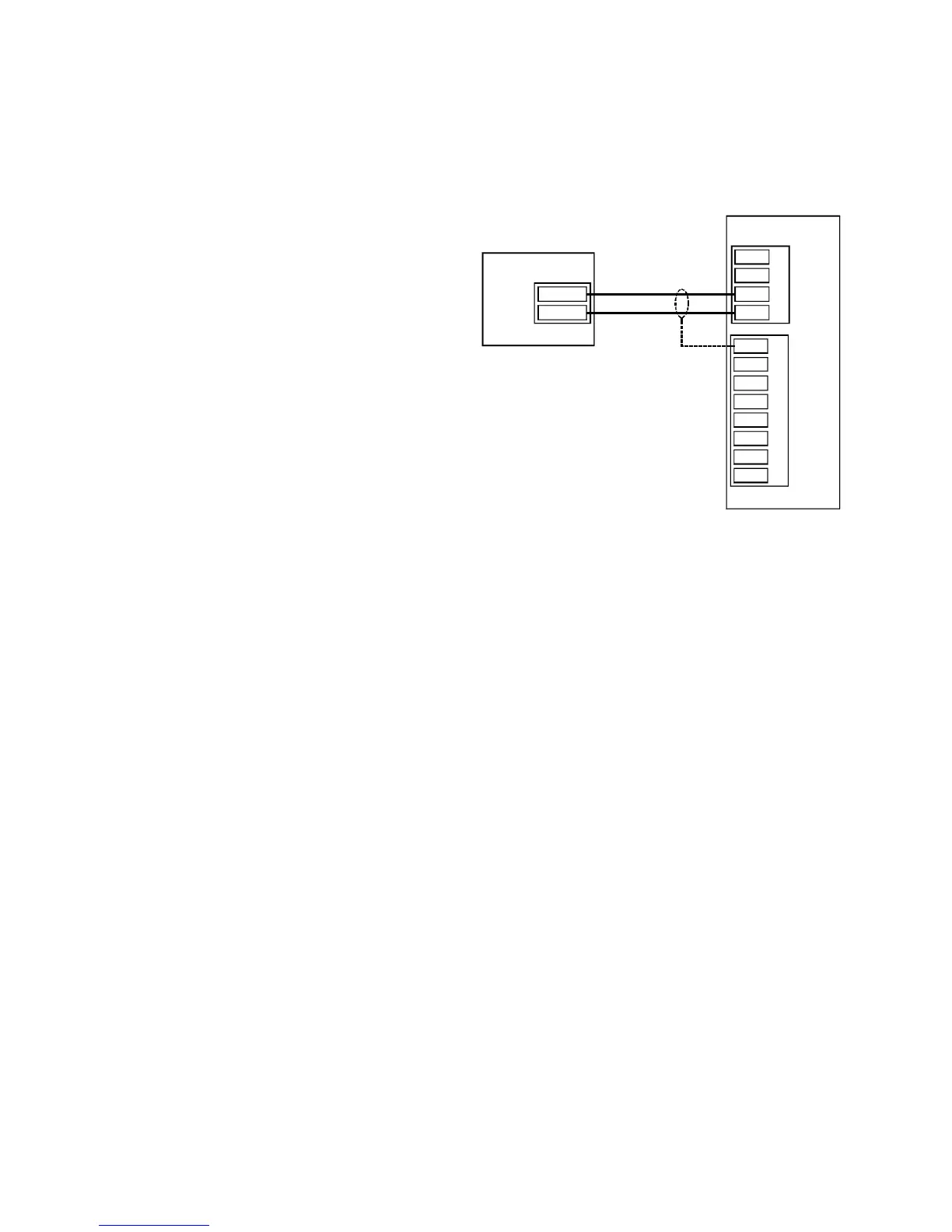
Figure 17 shows the wiring for this option. Up to 4 LevelCom 101s may be used as remote
readouts; they are daisy chained from the first LevelCom 101 shown in this wiring diagram.
Cable specified for RS-485 communication should be used for these connections.
Figure 17 Digital Communication Wiring
GND
ACK
GND
H.S.
GND
B 3
B 4
EXTERNAL BUTTONS
GND
A
B
C
D
PROC. INPUT
AOUT -
AOUT +
LevelCom 100
LevelCom 101
SHIELD