Page 33
©2013 Technical Marine Service, Inc. LC-100 V2.97
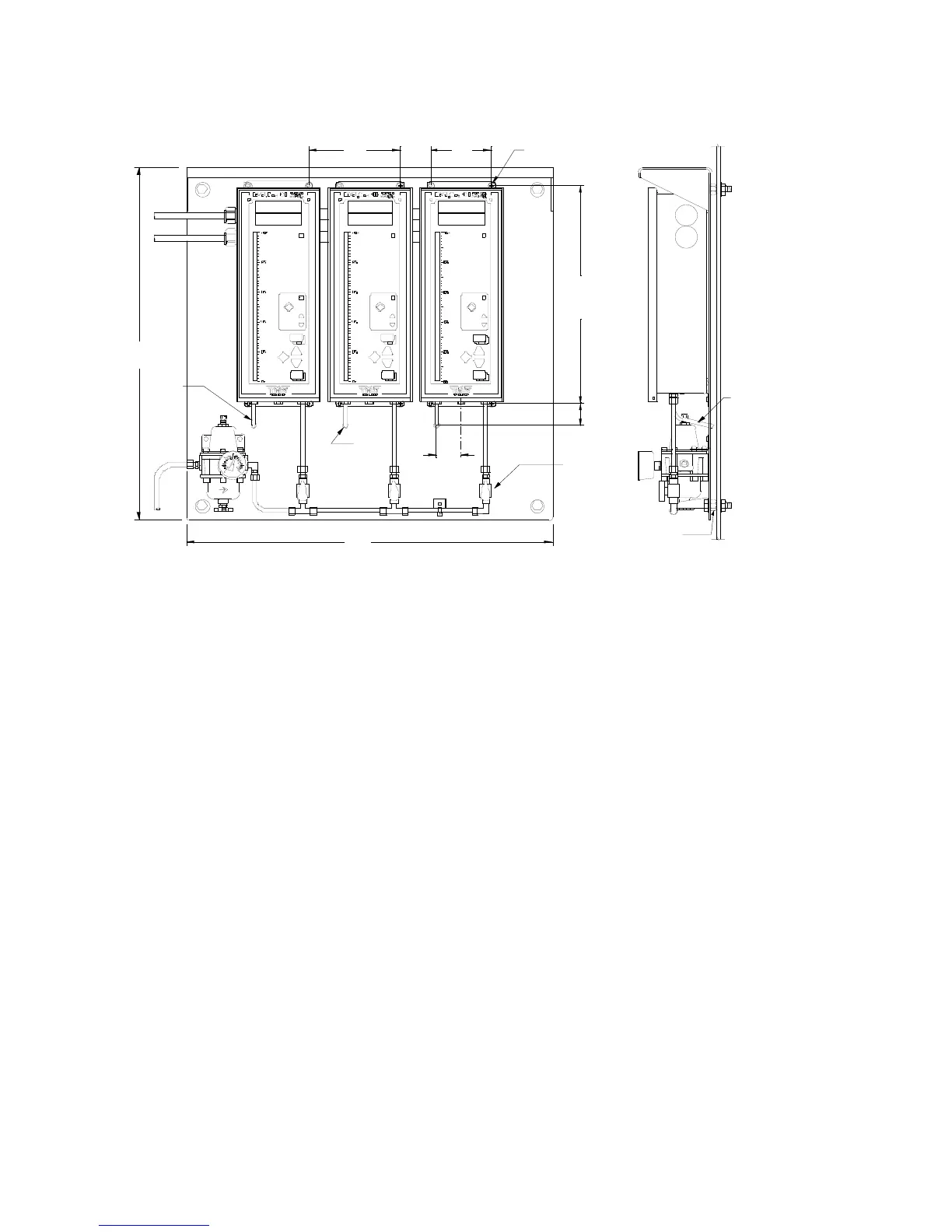
Important Note: Each LevelCom 100 must be fitted with a separate drain tube. Drain tubes
from multiple machines must not be connected together. The LevelCom 100 uses the drain
output to read ambient air pressure during a Hardware Zero operation. If drains are tied
together one machine may be purging to the drain while another machine is doing it’s
hardware zero operation, resulting in large errors, or Can’t Zero Sensor fault conditions.
Port 2 D.P. (Differential Pressure) is used when the Tank Pressure Compensation option has
been specified. It connects to the top of the tank in cases where the tank internal pressure is
different from ambient pressure at the LevelCom location. Tubing is to be made up tight and
leak free.
Port 3 TANK SENSE connects to the bubbler pipe in the tank. Tubing is to be made up tight
and leak free.
Port 4 S. G. (Specific Gravity) is used when the Automatic Specific Gravity option has been
specified. It connects to a second bubbler pipe in the tank, and is used only in applications
involving the optional automatic Specific Gravity calculating function. Tubing is to be made
up tight and leak free.
Port 5 SUPPLY should be connected to a clean, dry, source of control air, with the supply
pressure set depending upon the specified range of the LevelCom 100 (see the
specifications on page 2). Tubing is to be made up tight and leak-free. The LevelCom 100’s
Figure 19 Pneumatic Tubing Example
ACK
TR O U BL E
HI G H ALA RM
LO W A LAR M
UL L A G E
D
O
W
N
M
O
D
E
UP
S
HO
W
U
NI
TS
A
LT
E
RN
A
T
E
U
NI
TS
ACK
TROUBLE
HIGH ALARM
LOW ALARM
ULLAGE
D
O
W
N
M
O
DE
UP
S
H
O
W
U
N
IT
S
A
L
TE
R
N
AT
E
U
N
IT
S
ACK
TROUBLE
HIGH ALARM
LOW ALARM
UL L A G E
D
OW
N
M
O
D
E
UP
S
HO
W
U
NI
TS
A
LT
E
RN
AT
E
U
NI
TS
TA N K No .1
6
"
4
"
1
4
.
7
5
"
1
1
/
2
"
1
.
6
"
#10 SCREWS
2
4
"
2
4
"
11 /3 2"
HOL E
PLUG VALVE
DRAIN
TUBE
TANK No .2 TANK N o.3
DRAIN
TUBE
SPACER