Page 29
©2013 Technical Marine Service, Inc. LC-100 V2.97
Analog Output
The optional Analog Output is a 4-
20 mA current type. The output
may be internally powered, or
isolated and powered from an
external source, by changing three
circuit board jumpers. External
supply voltage may be up to 48
VDC. The jumpers are located on
the Sensor Input Circuit Board,
(LC100-A1, -A2, -A3). This board
is the larger circuit board mounted
to the Controller board (Figure 13).
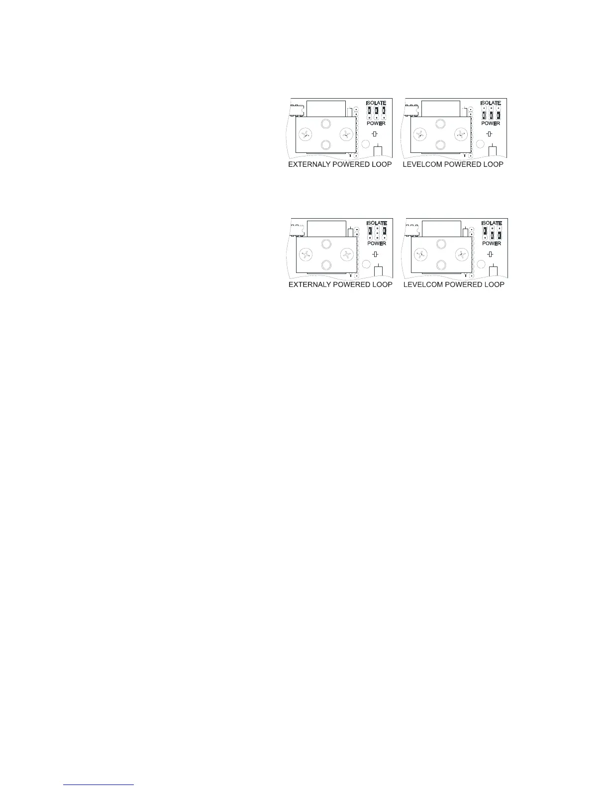
In the upper right-hand corner of
the Sensor Input Circuit Board are
three jumpers that have been
mounted onto pin headers, note the
labels ISOLATE and POWER
printed above and below the jumpers. You must identify the revision of Analog Circuit Board
in your machine; the jumper settings are different for different boards. You can read the
board type at the left edge of the Analog Circuit board (Figure 13). Figure 15 and Figure 16
show the jumper positions for the different board types. Move the jumpers as required.
Note: Failure to switch jumpers may cause damage to the circuit board.
The Analog Output connector is located at the top right of the main circuit board adjacent to
the Analog Input connector (Figure 13). The connector is a plug and socket. Pull the plug
out of the socket for ease in making up the connections. Be sure to observe polarity
markings.
Relay Output
Since the Relay Output is an option, this connector may not have been installed in your
LevelCom 100. If this option has been selected, the six-point connector can be found at the
right side of the LevelCom 100 enclosure centered horizontally on the Relay Module (Figure
13).
Note: When facing the relays Relay #1 is on the right, Relay #2 on the left.
Figure 15 Jumper Settings for -A1 and -A3
Figure 16 Jumper Settings for LC100-A2 Board