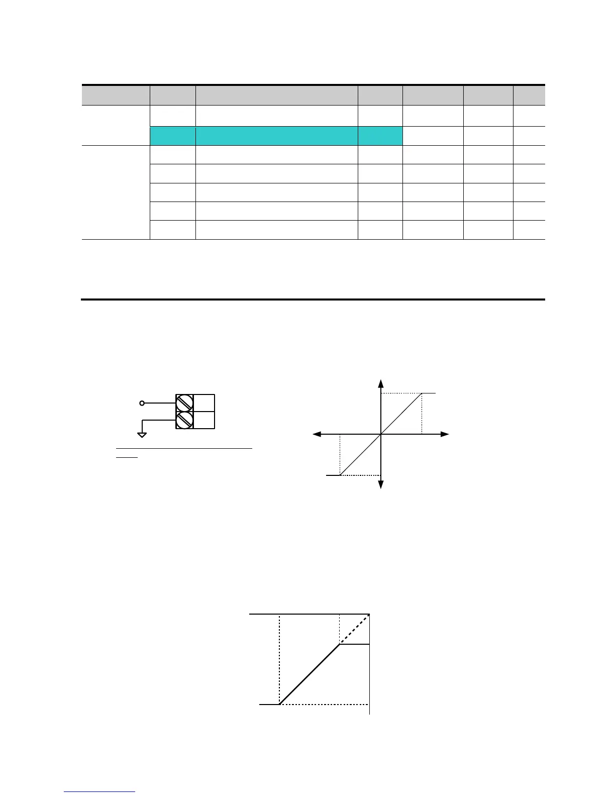
EasyManuals Logo

LSIS sv-ig5a User Manual

LSIS sv-ig5a
186 pages
To Next Page IconTo Next Page
To Previous Page IconTo Previous Page
Page #82 background imageLoading...
Page #82 background image
7-2
Frequency setting via 10 ~ +10[V] input
Group
Code
Parameter Name
Setting
Range
Initial
Unit
Drive group
0.00
[Frequency Command]
-
0 ~400
0.00
Hz
Frq
[Frequency Mode]
2
0 ~ 9
0
I/O group
I 2
[NV input minimum voltage]
-
0 ~ -10
0.0
V
I 3
[Frequency corresponding to I2]
-
0 ~ 400
0.00
Hz
I 4
[NV input max voltage]
-
0 ~ 10
10.00
V
I 5
[Frequency corresponding to I4]
-
0 ~ 400
60.00
Hz
I6 ~ I10
[V1 input]
Set Frq [Frequency Mode] to 2.
The set frequency can be monitored in 0.00 - [Frequency Command].
Apply 10V ~ +10V signal between V1 and CM terminal.
Output frequency corresponding to 10V ~ +10V input voltage to V1 terminal
I 2 ~ I 5: Setting input range and corresponding frequency to -10V ~ 0V V1 input voltage
Ex) when minimum (-) input voltage is -2V with corresponding frequency 10Hz and Max
voltage is 8V with run freq. 50Hz.
V1
CM
When using -10 ~ 10V from external
circuit
-10 ~ +10 V
Output freq
(Positive)
Output freq
(Negative)
Input
voltage
0~10[V]-10~0[V]
I 2I 4
I 3
I 5
Set freq.
V1 input
-8V -2V
10Hz
50Hz
For Service Call 800-848-2504

Table of Contents

Questions and Answers:

Question and Answer IconNeed help?

Do you have a question about the LSIS sv-ig5a and is the answer not in the manual?

LSIS sv-ig5a Specifications

General IconGeneral
BrandLSIS
Modelsv-ig5a
CategoryInverter
LanguageEnglish

Related product manuals