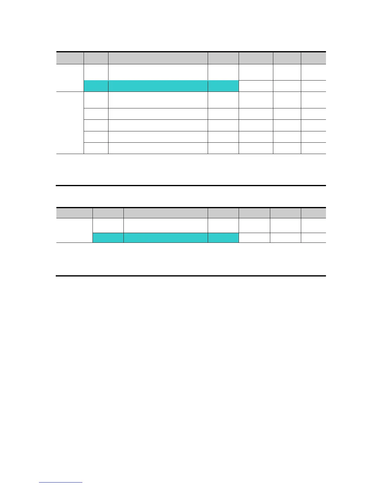
Frequency setting via 0 ~ 20 [mA] input
[Filter time constant for I input]
[I input minimum current]
[Frequency corresponding to I12]
[Frequency corresponding to I14]
Select 4 in Frq code of Drive group.
Frequency is set via 0~20mA input between I and CM terminal.
Frequency setting via -10 ~ +10[V] voltage input + 0 ~ 20[mA] input
Select 5 in Frq code of Drive group.
Override function available using Main/Auxiliary speed adjustment
Related code: I 2 ~ I 5, I 6 ~ I10, I11 ~ I15
Override function is to gain precise control and fast response by combining Main and Auxiliary
speed input. Fast response can be achieved by Main speed and precise control can be
accomplished by Aux. speed if the accuracy of Main/Aux speed is set differently.
Follow the setting below when Main speed is given via 0 ~ 20mA with Aux. speed via V1 terminal
(–10 ~ 10V).
When override function is used, select the Main/Aux. speed according to loads used.
For Service Call 800-848-2504
For Service Call 800-848-2504