Chap. 6 Analog I/O Module (XBF-AH04A)
(4) Sample Output Program (for IEC type)
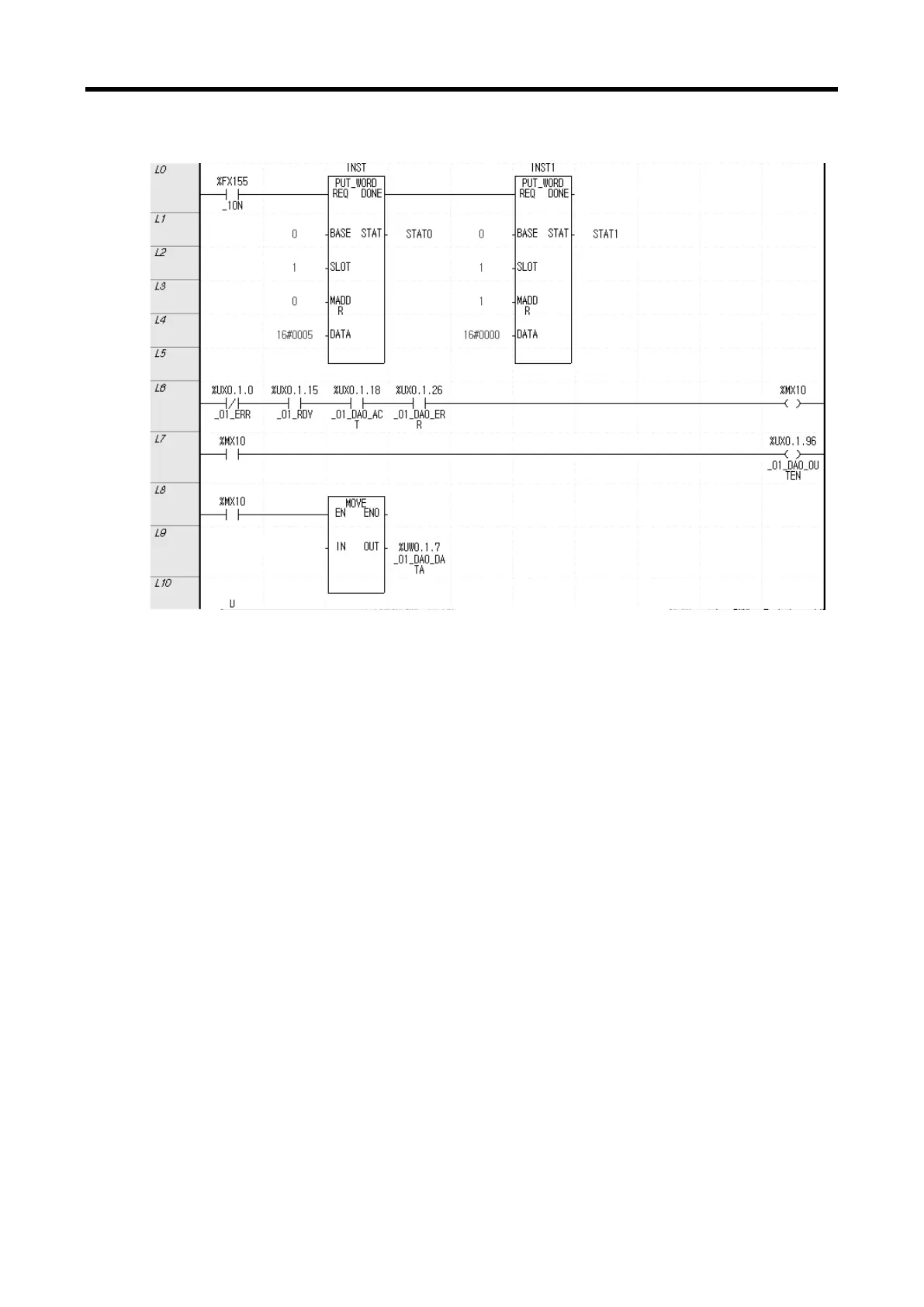
(a) Using PUT command to write h0005 in the address 0, slot 1 to operate Input Channel 0 and
Output Channel 0.
(b) Using PUT command to write h0000 in the address 1, slot 1 to set the input range of Input
Channel 0 to DC 4 ~ 20mA and the output range of the Output Channel 0 to DC 4 ~ 20mA.
(c) When the module is in normal operation, %MX10 is turned on.
%UX0.1.0(Module Error) = Off
%UX0.1.15(Module Ready) = On
%UX0.1.18(Output Channel 0 in-operation) = On
%UX0.1.26(Output Channel 0 Error) = Off
(d) When %MX10 is on, Channel 0 Output Status setting (%UX0.1.96) is turned on and output is
permitted.
(e) When %MX10 is on, data of the ‘Channel 0output’ variable is transferred to Output Channel 0
Input Value (%UW0.1.7) and outputted.
6 - 45