Chapter 10 Analog I/O Option Board (XBO-AH02A)
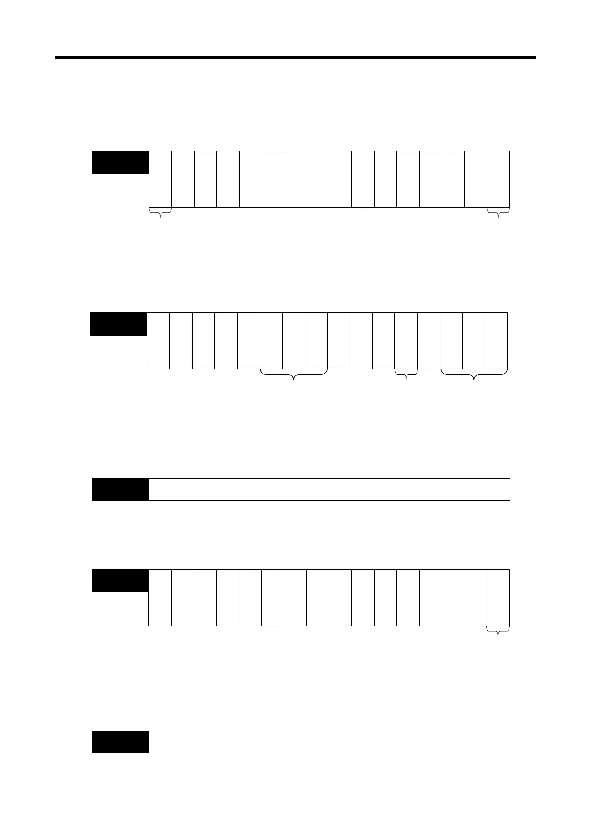
(1) Module Ready/Error Flag ( ( ) is for IEC types, y: slot No.)
(a) U0y.00.F(%UX0.y.15): at power on or reset of PLC CPU, turns on when the analog I/O
conversion is ready and analog conversion is performed.
(b) U0y.00.0(%UX0.y.0): the flag indicating the error status of analog input option board module.
bit15 bit14 bit13 bit12
bit11
bit10
bit9
bit8
bit7
bit6
bit5
bit4
bit3
bit2 bit1 bit0
-
-
--
----
-
-
-
U0.00
UW0..0)
Error occurrence
information
Bit On (1): error
Bit Off (0): Normal
-
-
-
Module READY
Bit On (1): Normal
Bit Off (0): error
(2) Operation channel information/ channel error information flag ( ( ) is for IEC types, y: slot No.)
This is the area for storing the operation information and channel error information by channel.
bit15
bit14
bit13
bit12 bit11 bit10 bit9 bit8 bit7 bit6
bit5
bit4
bit3
bit2
bit1
bit0
- -
O
u
t
p
u
t
C
H
0
I
n
p
u
t
C
H
0
------
U0.01
UW0..1)
Operating CH
information
Bit On (1): operating
Bit Off (0): stop
I
n
p
u
t
C
H
0
-
-
O
u
t
p
u
t
C
H
0
I
n
p
u
t
C
H
0
CH error information
Bit On (1): error
Bit Off (0): normal
CH disconnection
Bit On (1): disconnection
Bit Off (0): normal
-
(3) Digital Output Values ( ( ) is for IEC types, y: slot No.)
(a) A/D converted digital values are outputted to buffer memory address U0y.04
(b) Digital output values are saved in 16-bit binary figures.
bit15
bit14 bit13
bit12 bit11
bit10
bit9
bit8
bit7 bit6
bit5 bit4
bit3
bit2
bit1 bit0
Input CH0 conversion value
U0.04
UW0..4)
(4) Output setting ( ( ) is for IEC types, y: slot No.)
(a) Each channel can be specified enable/disable the analog output.
(b) If the output is not specified, output of all the channels will be disabled
bit15 bit14
bit13 bit12
bit11
bit10 bit9 bit8
bit7 bit6
bit5 bit4
bit3 bit2
bit1 bit0
-
O
u
t
p
u
t
C
H
0
-
--
-
--
U0.06
UW0..4)
Output status setting
Bit On (1): enable output
Bit Off
(0): disable output
-
---
---
-
(5) Digital input ( ( ) is for IEC types, y: slot No.)
(a) Digital input value can be selected and used within the range of unsigned value (0~4047),
signed value (-2000~2047), precise value and percentile value (0~1011) based on input type.
(b) If the digital input value is not specified, it will be set to 0.
bit15 bit14 bit13
bit12 bit11 bit10 bit9 bit8
bit7 bit6 bit5 bit4
bit3 bit2 bit1 bit0
Output CH0 input value
U0.07
UW0..7)
10 - 33