Chapter 13 Analog Input Module (XBF-AD04C)
13.6.6 Alarm function
When the input signal is exceeded from valid value, the alarm will be shown through alarm flag of
relevant channel.
1)
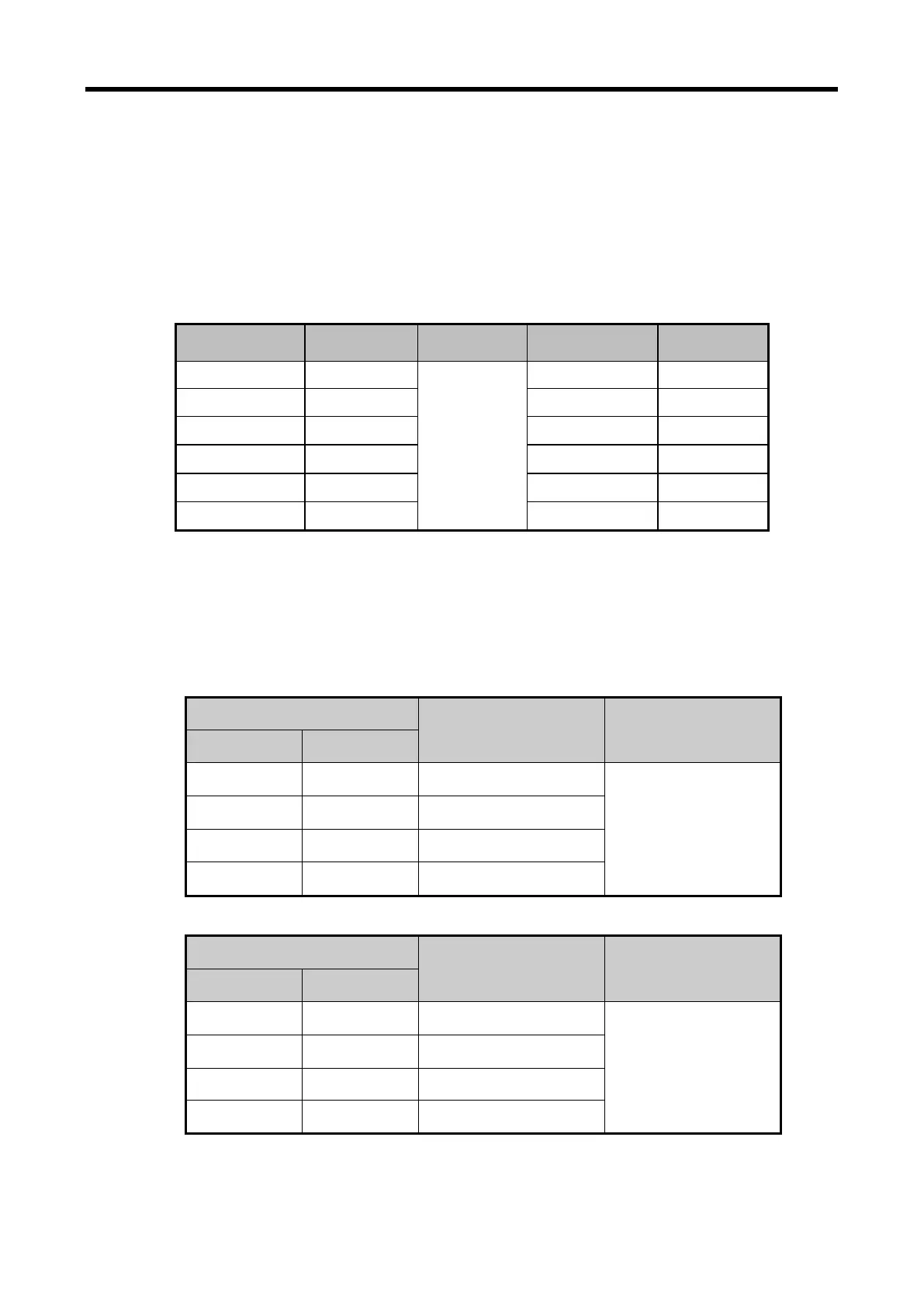
Input detection function
Detection condition for each input signal range is as below.
Difference
Low limit High limit
4 ~ 20㎃ 16㎃
1.2%
3.808㎃ 20.192㎃
0 ~ 20㎃ 20㎃ -0.24㎃ 20.24㎃
1 ~ 5V 4V 0.952V 5.048V
0 ~ 5V 5V -0.06V 5.06V
0 ~ 10V 10V -0.12V 10.12V
-10 ~ 10V 20V -10.24V 10.24V
2)
Alarm sign of each channel
Alarm detection signal about each input channel is shown on U0y.11 and U0y.12. If the input
signal come back, the alarm detection sign will automatically come back. (The 'y' is the slot
number of equipped modules.)
(1) High limit alarm (U0X.11)
Device assignment
Description Status description
XBM/XBC XEC
U0y.11.0 %UX0.y.176 Channel0 high limit alarm
Off: Normal
On: Maximum alarm
occurrence
U0y.11.1 %UX0.y.177 Channel1 high limit alarm
U0y.11.2 %UX0.y.178 Channel2 high limit alarm
U0y.11.3 %UX0.y.179 Channel3 high limit alarm
(2) Low limit alarm (U0X.12)
Device assignment
Description Status description
XBM/XBC XEC
U0y.12.0 %UX0.y.192 Channel0 low limit alarm
Off: Normal
On: Maximum alarm
occurrence
U0y.12.1 %UX0.y.193 Channel1 low limit alarm
U0y.12.2 %UX0.y.194 Channel2 low limit alarm
U0y.12.3 %UX0.y.195 Channel3 low limit alarm
13 - 15