XGB Analog edition manual
13.7.2 Notices in wiring
(1) Do not put the power line near the external I/O signal line of analog input module. You have to
secure enough distance to avoid the interruption from the induced noise and the surge.
(2) The wire has to select by considering permitted current and the ambient temperature.
The maximum wire size is good in case of AWG22 (0.3㎟) or more.
(3) When the wire is so near with high temperature machines and materials and touched with oil for
a long time, it can be short circuit and malfunction.
(4) When doing terminal ports wiring, check the polarity.
(5) In case that the high voltage line and the power line are wired at the same time, the induced
interruption is caused. So it can be a reason for breakdown.
13.7.3 Example for the wiring
(1) The input resistance of current input circuit is 250Ω (typ.).
(2) The input resistance of voltage input circuit is 1 MΩ (min.).
(3) Set the operation mode only if you want to use channels.
(4) The analog input module doesn't provide the power for input device.
Use the external power device.
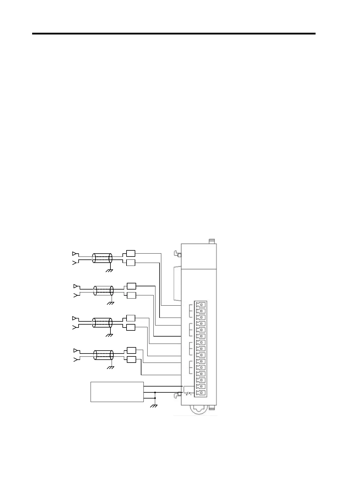
(5) Example for analog input wiring
When inputting the voltage, relevant channel V+ and COM terminal is used. When inputting
the current, relevant channel V+ and COM terminal is used after connecting between V+ and I+
terminal.
a) Voltage wiring
XBF-AD04C
RUN
XBF-AD04C
DC24V
-10~10V
0~20mA
V0+
I0+
COM0
V1+
I1+
COM1
V2+
I2+
COM2
V3+
I3+
COM3
CH0
+
-
CH1+
-
CH0 -
CH2
+
-
CH3
+
-
CH0+
CH1 -
CH1+
CH2 -
CH2+
CH3 -
CH3+
V0+
COM0
V1+
COM1
V2+
COM2
V3+
COM3
DC24V+
DC24V-
DC Power
(For analog module)
PE
※ DC power for analog power supply have to connect DC24V- with PE.
13 - 18