MAINTENANCE/SERVICE
Traction Drive: Neutral Set-Up Procedure
This procedure should be performed only after
the
nine
preceding checks
and
adjustments
have
failed
to
so
lve
the
neutral lock/stee
ring
problem
.
This procedure will eliminate mach
in
e movement
in
neutral and will improve neutral
lo
cking ability.
A
A
CAUTION:
Use
jack-stands with a
minimum capacity
of
3 tons (2720
kg)
to
provide
adequate
support
for
machine.
DANGER: Never attempt neutral
set-up procedure
without
raising
front
wheels
off
the
ground
so
they
are free 10
tum
. Failure to raise
front
wheels
will
result in machine runaway,
causing severe personal injury
or
death.
1.
Detach header and remove hay conditioner
formi
ng
shields from under tractor.
2.
Raise front
of
machine high enough to allow
both wheels to turn freely and support with
jack-stands.
See "Jacking Procedure" under
Wheel & Tire Maintenance in this section.
3.
Start engine and idle at approximately
12
00-
1500
RPM
.
4. Set controls as follows:
Ground speed lever in neutral.
Steering wheel locked.
• Park brake disengaged.
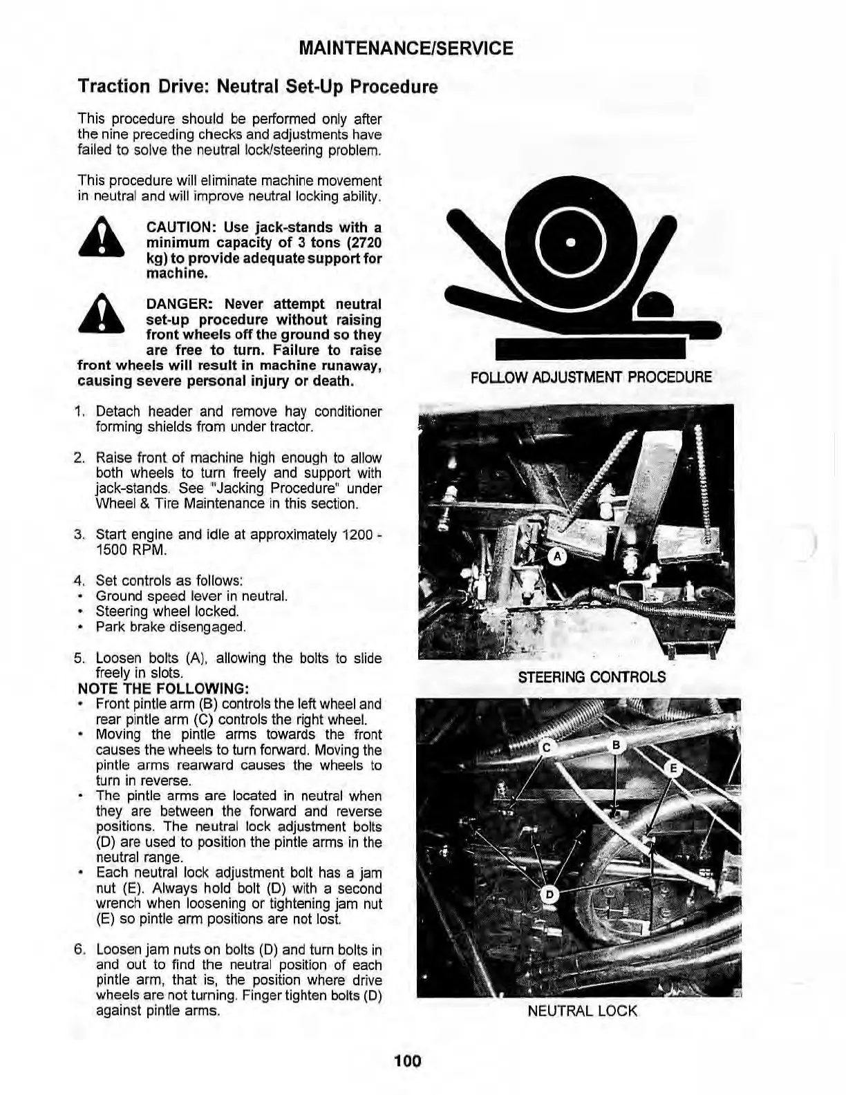
5.
Loosen bolts (A), allowing the bolts to slide
freely in slots.
NOTE
THE
FOLLOWING:
Front pintle a
rm
(8)
controls the left wheel and
rear pintle arm (C) controls the right
wheel.
Moving the pintle arms towards the front
causes the wheels to turn forward. Moving the
pintle arms rearward causes the wheels to
turn in reverse.
The pintle arms are located in neutral when
they are between the forward and reverse
positions. The neutral lock adjustment bolts
(D) are used to position the pintle arms
in
the
neutral range.
Each neutral lock adjustment bolt has a jam
nut (E
).
Always hold bolt
(0)
with a second
wrench when looseni
ng
or tightening jam nut
(
E)
so pintle arm positions are not lost.
6.
Loosen jam nuts on bolts (D) and turn bolts
in
and out to find the neutral position of each
pintle arm, that is, the position where drive
wheels are not turning. Finger tighten
bolts (D)
against pintle arms.
100
FOLLOW
ADJUSTMENT
PROCEDURE
STEERING
CONTROLS
NEUTRAL
LOCK
)