TRANSMISSION AND TORQUE CONVERTER CD3340B/YB4411
7-42
Published 04/07/2015 Control # 569-00
d. Calculate the required thickness of shims to give the
correct end play, which should be 0.03 - 0.08 mm
(0.001 - 0.003 in).
12. Separate the two casing halves and add or subtract
shims (34, Figure 7-49) installed beneath the outer
races in the rear (output) case 32 to correct input and
forward shaft end float. Repeat steps 10 and 11, or 12
and 13 to recheck the end play.
NOTE: Production transmissions have the shims installed
in the front case; however when servicing the
transmission, it is permissible to install shims (34)
in the rear case as shown.
When correct end play has been achieved, remove the input
and reverser clutch shafts and install piston ring seals 46
removed in step 6.
NOTE: Do not reinstall the input and forward clutch shafts
at this time. They must be installed with the other
shafts into the transmission - see steps 13 to 15.
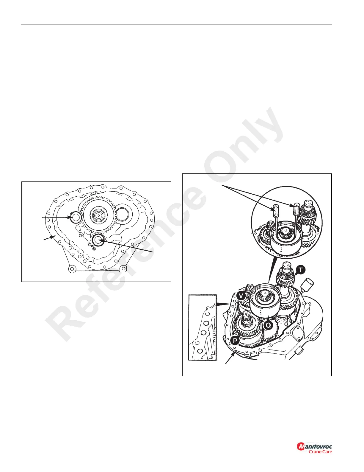
13. Install input clutch (V, Figure 7-50) and main shaft (Q)
simultaneously into the front case as shown. Before
installing make sure that all the piston ring seals have
been replaced with new seals and lightly greased and
fully seated in their grooves. (See PTFE Piston Ring
Seal Installation Procedure). Also ensure that both the
input clutch and main shaft taper roller bearings have
been coated with a Lithium Base, E.P. No. 2 bearing
grease.
a. Install all remaining bearing cups. Install main shaft
end spacer 50. DO NOT install O-rings at this point.
See NOTE below.
End spacers have extraction holes to assist
removal. Install the spacer with the extraction holes
facing towards you.
NOTE: This is a preparatory step for setting the main shaft
end play. At a later point it will be necessary to
remove the end spacer so that shims can be
installed to set the end play. If the O-rings are left
on at this point, the spacer will be difficult to
remove. New O-rings are installed after the correct
main shaft end play has been set.
b. Install the end play setting tool P/N 1900449
(Figure 7-15) over the main shaft end bearing and
spacer. Tighten the bolts to 52 Nm (42 lb-ft).
14. This step requires the help of an assistant. Have the
assistant SLIGHTLY raise and tilt the input clutch V and
mainshaft Q. While the assistant is holding the two units,
install forward clutch (P).
15. Coat the layshaft taper roller bearings with a Lithium
Base, E.P. No. 2 bearing grease and install the layshaft
assembly (T) into the front case.
The arrangement of the clutch assemblies should now
be as shown in Figure 7-50. Make sure all bearings are
fully seated, and that the relevant gears have meshed
correctly.
16. Using two small rods or screwdrivers (A, Figure 7-50),
align all the friction/counter plates of the main shaft
clutch.
17. Install three new O-rings (33) in the front case (49). Coat
the O-rings with grease to hold in position.
Reference Only
 Loading...


