GROVE 7-43
CD3340B/YB4411 TRANSMISSION AND TORQUE CONVERTER
Published 04/07/2015 Control # 569-00
NOTE: Do not apply an excessive amount of Loctite 574
around the O-rings. Too much can dislodge the
O-rings.
18. Apply Loctite 574 to the front case mating face. Prior to
installing the rear case, ensure that all bearings have
been coated with a Lithium Base, E.P. No. 2 bearing
grease. Ensure that all piston ring seals are fully seated
and have been coated with grease.
19. Make sure all the friction/counter plates in the main shaft
clutch are aligned (see Step 16). Carefully lower the rear
(output) case into position, taking care to align the output
gear splines with the main shaft clutch friction/counter
plates. If the casing does not drop down onto the
dowels, gently rotate the disc back and forth to center
the plates. Apply Loctite 243 to bolts and tighten to a
torque of 56 Nm (42 lb-ft).
NOTE: To aid in assembly of the rear case, use tool P/N
1903746 (Figure 7-19) and an airline to clamp the
pack and hold it position when lowering rear case
into position.
Do not use the retaining bolts or external force to
close the casing joint or the plates will be damaged.
20. Using a new gasket (28, Figure 7-51), temporarily install
the layshaft end cap (27) and shims (29). Tighten
retaining bolts (26) to a torque of 56 Nm (42 lb-ft).
NOTE: Installing the layshaft end cap at this stage is a
temporary arrangement to enable the
measurement of the layshaft end play. Do not apply
Loctite 243 to the retaining bolts at this time.
NOTE: Take care not to damage the gasket because it
must be used during final assembly.
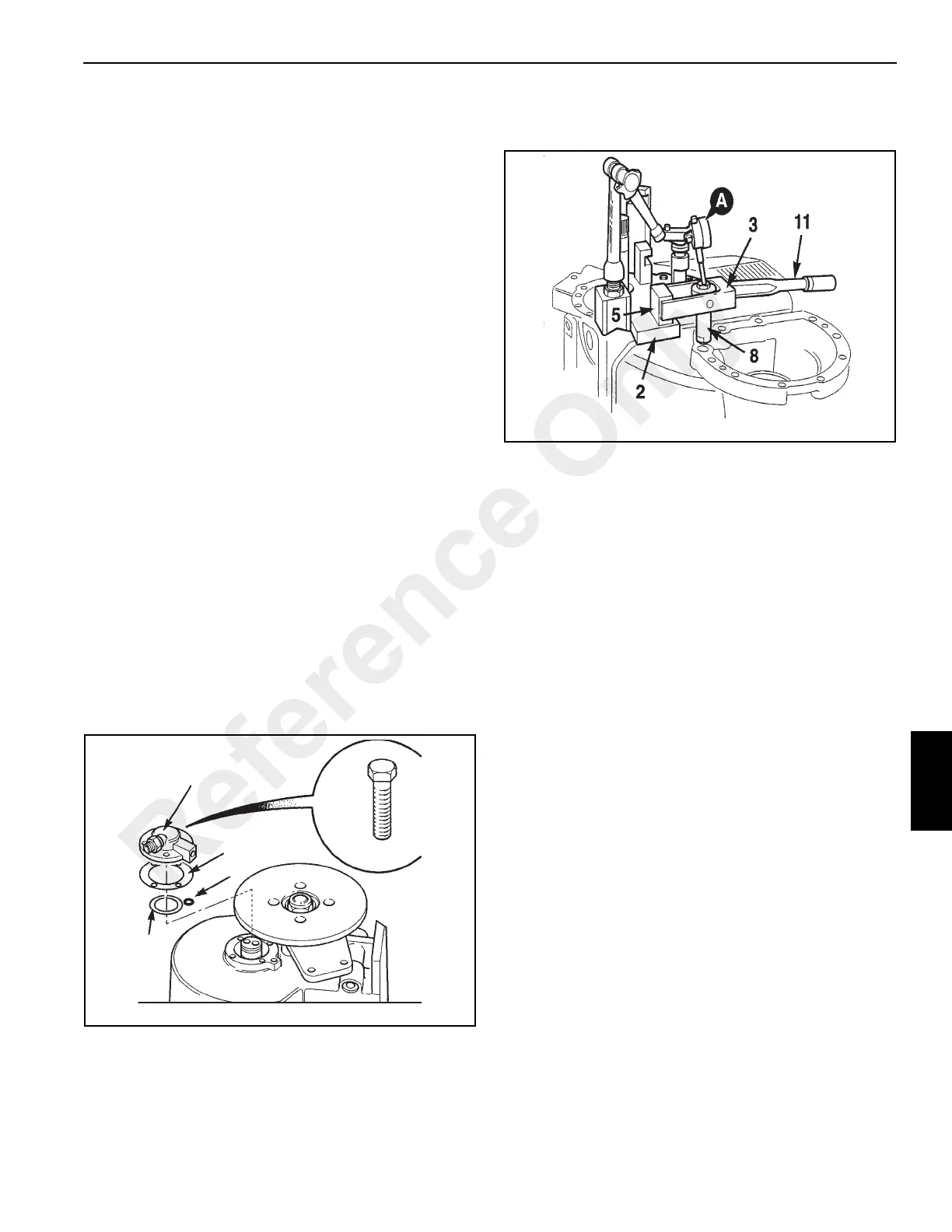
21. Measure the end play for the layshaft using the end play
checking kit.
NOTE: Numbers in Figure 7-52 correspond with numbers
in Figure 7-24.
a. Place the transmission on a work bench with the
input side up so that the drive shaft mounted flange
can be turned.
b. Secure base plate 2 on the face of the casing using
existing tapped holes for the mounting bolts. Tighten
the bolts to a torque of 56 Nm (42 lb-ft).
c. Select adapter 8 from the kit (Figure 7-24) and
screw it into the tapped hole in the layshaft.
d. Locate yoke 3 and wrench 11 into adapter 8 and
pillar 5. Set the wrench to 35 Nm (26 lb-ft).
e. Using a magnetic block, mount a dial test indicator
(DTI) A with the probe on the head of adapter 8 and
adjust to zero.
f. While rotating the layshaft back and forth using the
flange on output shaft to seat the bearings, lift and
depress wrench 11 and note the reading on the DTI.
g. Remove wrench 11 and adapter 8 from the layshaft
assembly.
h. Calculate the required thickness of shims to give
correct end play, which should be 0.03 - 0.08 mm
(0.001 - 0.003 in). The end shaft play should be set
as near as possible to the minimum tolerance.
22. If the end play checking kit is not available, use the
following procedure.
Set up a dial test indicator (DTI) as shown in Figure 7-55
on a suitable M10 bolt and measure layshaft end play,
which should be 0.03 - 0.08 mm (0.001 - 0.003 in).
Rotate the shaft (using the flange) while measuring to
seat the bearing fully.
NOTE: When measuring the end play, rotate the flange on
2WD transmissions.
FIGURE 7-51
a0822
27
26
28
30
29
Reference Only
 Loading...


