GROVE 8-31
CD3340B/YB4411 AXLES/DRIVE SHAFTS/WHEELS AND TIRES
Published 04/07/2015 Control # 569-00
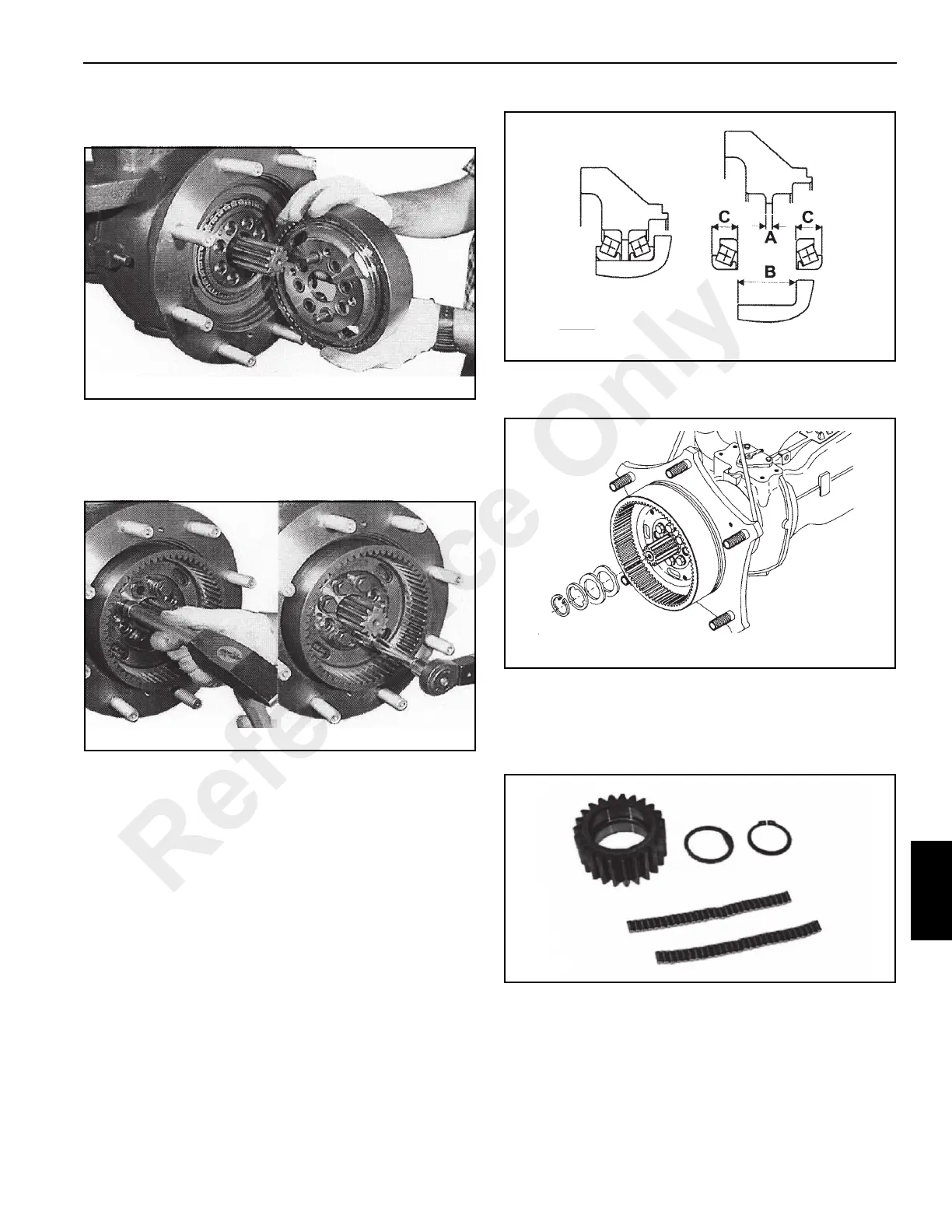
9. Install the wheel carrier assembly on the wheel hub
using the two projecting bushings as dowel pins
10. Drive the dowel bushings flush using SPECIAL TOOL P/
N 1901776 and a hammer (Figure 8-127).
Install the wheel carrier mounting screws and tighten to
a torque of 120 Nm (88 lb-ft).
11. The installation of the wheel carrier does not require any
pre-loading or backlash adjustments. Although, when
installing new components check the dimensions shown
in Figure 8-128.
A = 5.900 - 5.950 mm (0.232 - 0.234 in)
B = 52.229 - 52.279 mm (2.056 - 2.058 in)
C = 23.070 - 23.172 mm (0.908 - 0.912 in)
12. Install the rings and shim onto the axle shaft and lock
with the retaining ring (Figure 8-129).
Epicyclic Reduction Gear Assembly
1. Gather all the components of the epicyclic planetary
gear assembly (Figure 8-130). Be careful not to loose
any of the rollers.
Reference Only
 Loading...


