S
ection
2
1 - 3 Phase
Sensing
LED #2
This LED blinks slowly when selecting single or three phase sensing via the front panel
push buttons. When in this adjustment mode, LED #1 is on if single phase sensing is
selected, LED #3 is on if three phase sensing is selected.
Coarse Voltage
LED #1
This LED blinks slowly when the “Coarse Voltage” level is selected for adjustment via the
front panel push buttons.
Setting Level Indication
Indication of a setting level is provided by the 12 front panel LED indicators. The upper limit of a setting range is
represented by the top LED which is labeled GEN/LAG and MAX. The lower limit of a setting range is represented
by the bottom LED which is labeled MIN and ABSORB/LEAD. The setting range for each LED is summarized in
Tables 2-4 through 2-15. LEDs in the tables are numbered from 1 to 12 with 1 being the lowermost LED (labeled
MIN/ABSORB/LEAD) and 12 being the uppermost LED (labeled GEN /LAG/MAX.
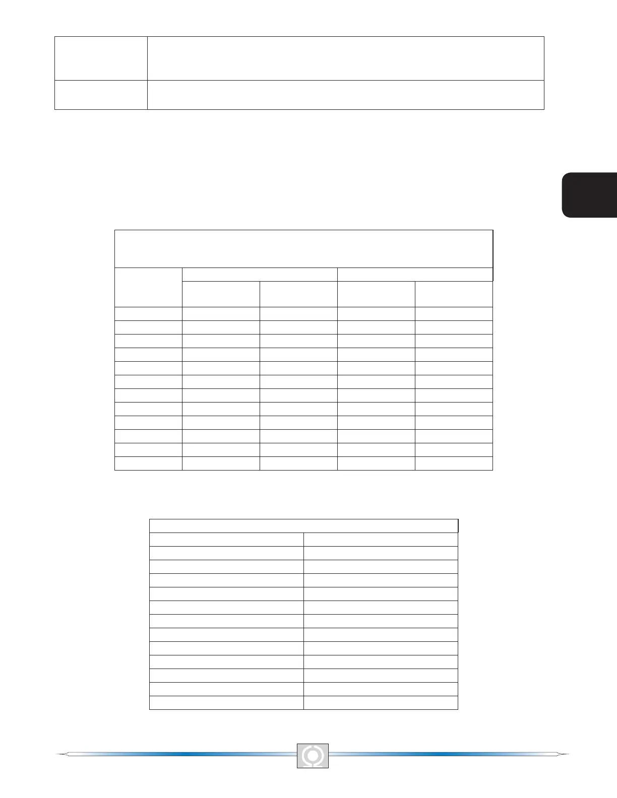
Table 2-4. Coarse Voltage Adjust Setting Ranges
Coarse Voltage – LED 1 Blinking Slowly
Maximum Adjustment Range
Increment: 6 Vac
LED
Increase Decrease
Minimum
Value
Maximum
Value
Minimum
Value
Maximum
Value
12 563 600 558 600
11 521 557 516 552
10 479 515 474 510
9 437 473 432 468
8 395 431 390 426
7 353 389 348 384
6 311 347 306 342
5 269 305 264 300
4 227 263 222 258
3 185 221 180 216
2 143 179 138 174
1 95 137 95 132
Table 2-5. Sensing Mode (Single-phase/Three-phase) Select
Single-phase/Three-phase select – LED #2 Blinking Slowly
LED MODE
12 N/A
11 N/A
10 N/A
9 N/A
8 N/A
7 N/A
6 N/A
5 N/A
4 N/A
3 Three-phase
2 N/A
1 Single-phase
10
5
Section 2 Index
3
Main Index
11
3
Main Index
5
Section 2 Index