S
ection
5
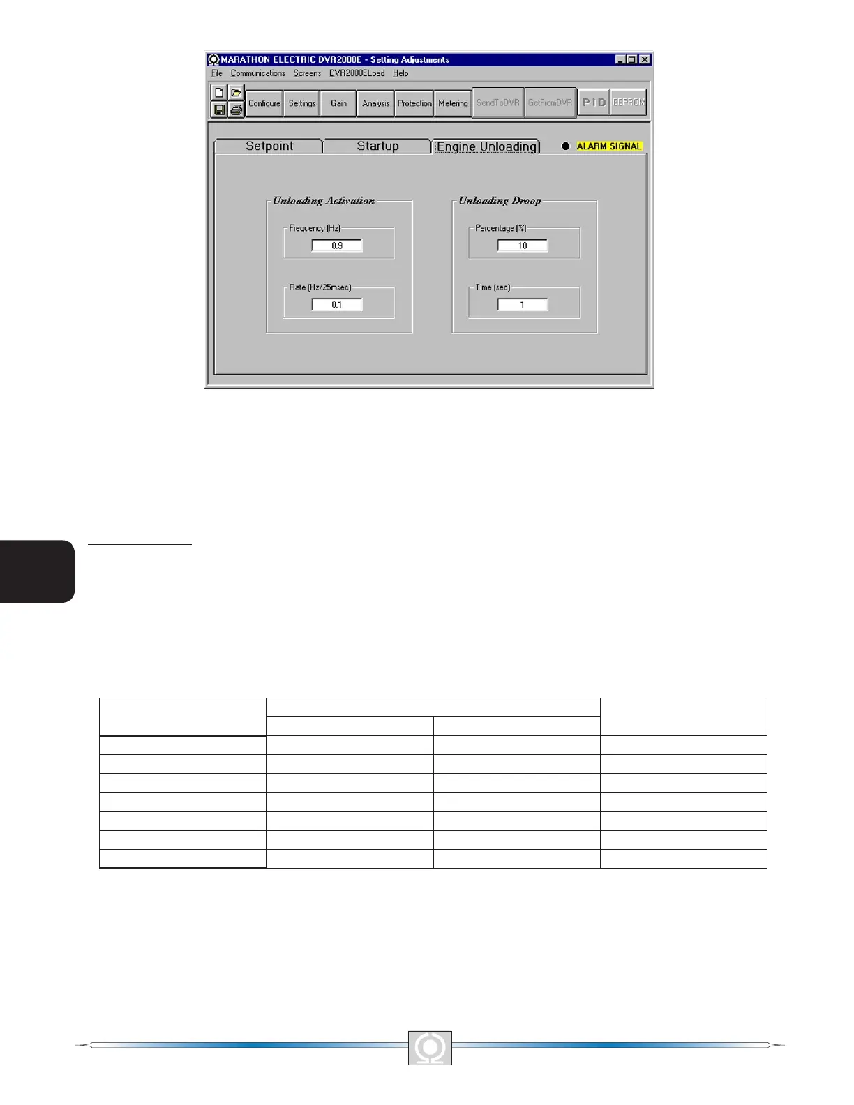
Figure 5-11. Setting Adjustments Screen, Engine Unloading Tab
Control Gain
The Control Gain screen consists of one tab labeled Control Gain. Click the Gain button to access the Control
Gain screen or click Screens on the menu bar and click Control Gain.
Control Gain Tab
Control gain settings are shown in Figure 5-12 and are described in the following paragraphs.
Stability Range. This setting selects one of 7 preset stability ranges within the DVR2000E. A guide for selecting
the stability range is provided in Table 5-1. A setting of 21 enables the entry of custom stability settings through the
MARATHON-DVR2000E-32 PID window. Information about the PID window is provided later under the heading of
PID Window. When the Stability Range is set at 21, the PID button may be selected to access the PID window. A
Stability Range setting of 1 through 7 disables the PID button and prevents access to the PID window.
Table 5-1. DVR2000E Stability Range Settings
Frame/Poles
Time Constants
Stability Range
Generator (T’do) Exciter (Texc)
360/4 1.0 0.17 1
430/4 1.5 0.25 2
570/4 2.0 0.33 3
740/4 2.5 0.42 4
1,000/4 3.0 0.50 5
740/6 3.5 0.58 6
1,000/6 4.0 0.67 7
AVR/FCR - Proportional Gain KP. This setting selects the proportional constant (KP) stability parameter. The
DVR2000E supplies a value that is equivalent to KP multiplied by the error between the voltage setpoint and the
actual generator output voltage. KP values of 0 to 1,000 may be entered in increments of 0.01.
Observe the following guidelines when tuning the KP value. If the transient response has too much overshoot,
then KP should be decreased. If the transient response is too slow, then KP should be increased.
48
3
Main Index
5
Section 5 Index
49
3
Main Index
5
Section 5 Index