S
ection
4
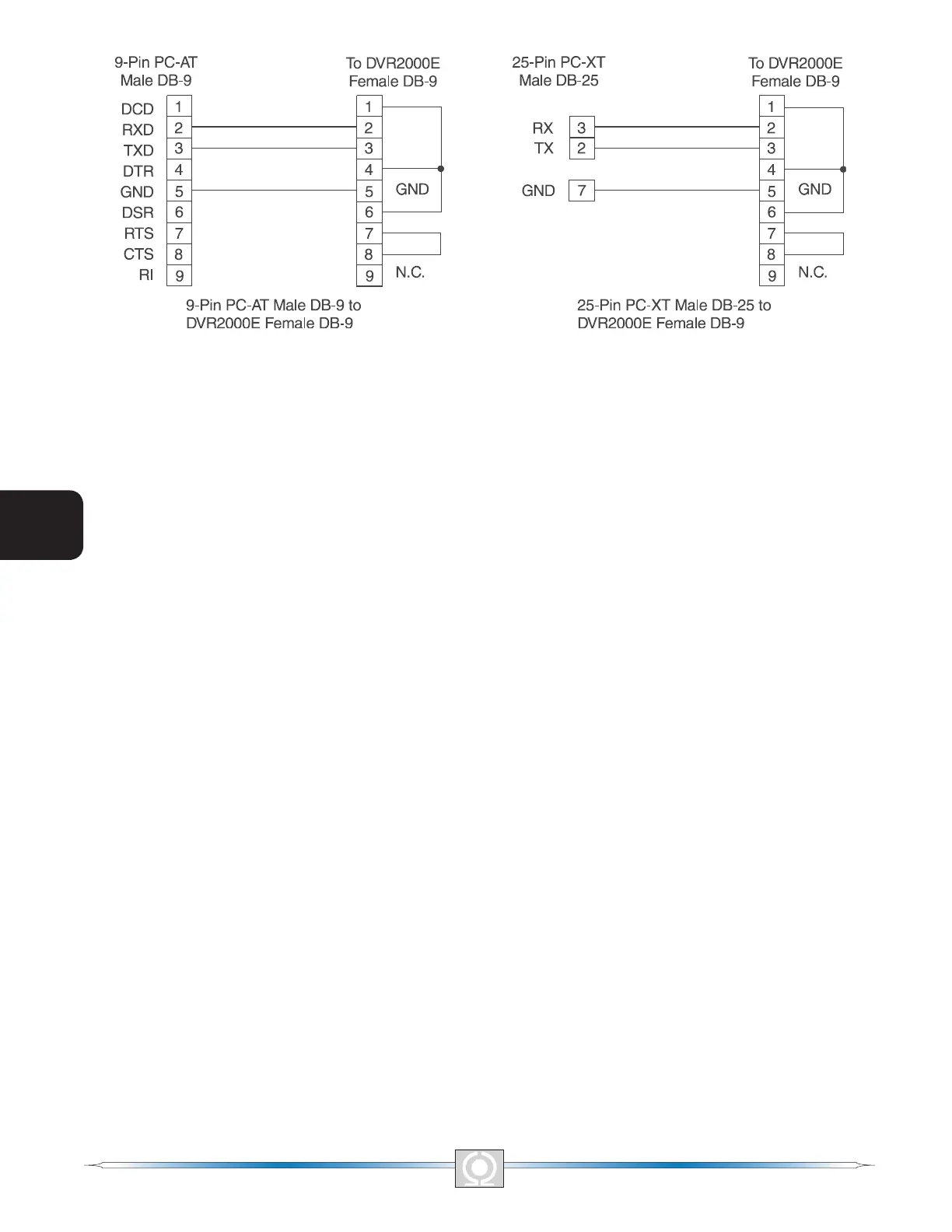
Figure 4-5. Personal Computer to DVR2000E Connections
DVR2000E Connections for Typical Applications
Figures 4-6 through 4-9 illustrate typical applications using the DVR2000E. Figure 4-6 shows an application where
the DVR2000E is connected for three-phase voltage sensing. Figure 4-7 shows an application with single-phase
voltage sensing while Figure 4-8 illustrates an application with a single-phase generator.
Figure 4-9 illustrates the connection of two DVR2000E devices used in a Cross-Current (Reactive Differential)
application. Note that the .1 ohm resistor shown may have to vary. When operating in parallel reactive differential
mode (cross current), attention must be paid to the use of the burden resistor shown in Figure 4-9. The burden
resistor should have a value approximately 10 times the cross current loop resistance for proper differential
operation. The value of 0.1 ohm is a suggested value. The volt-ampere (VA) capacity of the paralleling current
transformers should be considered after sizing the burden resistor.
32
3
Main Index
5
Section 4 Index
33
3
Main Index
5
Section 4 Index