S
ection
5
Analysis
Click the Analysis button or click Screens on the Menu bar and click Analysis to view the Analysis screen. The
Analysis screen consists of four tabs: VAR, PF, AVR, and FCR. Each of the tabs displays four metered sensing
values and has six alarm signal indicators. Metered sensing values include Vrms (rms voltage), Ifd (dc eld
current), reactive power (vars), and power factor (PF). Alarm signal indicators include Overexcitation Shutdown,
Generator Overvoltage, DVR Overtemperature, Loss of Generator Sensing, Overexcitation Limiting, and
Underfrequency Active.
The operating status and control mode of the DVR2000E determine which tabs of the Analysis screen are enabled
and can be accessed by the user. Table 5-2 lists the DVR2000E operating status and control modes that enable
the four tabs of the Analysis screen.
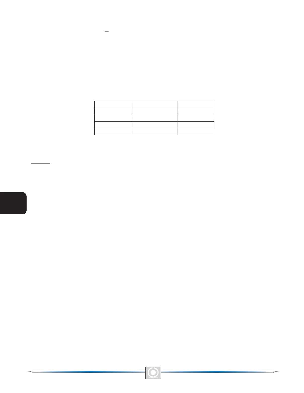
Table 5-2. Analysis Screen Tab Combinations
Control Mode Operating Status Tab Enabled
AVR OFF AVR
AVR PF AVR, PF
AVR VAR AVR, VAR
FCR N/A FCR
Control mode and operating status selections are made at the Operation tab of the MARATHON-DVR2000E-32
Metering screen and are discussed later in this section.
AVR Tab
Figure 5-13 illustrates the settings, sensing values, and alarm signal indicators of the AVR tab. The settings of the
AVR tab make it possible to increment and decrement the AVR setpoint of the DVR2000E. The sensing values and
alarm signal indicators of the AVR tab are also displayed by the other tabs of the Analysis screen.
Voltage Step Response - AVR Setpoint (V) (Nominal). This read-only eld indicates the AVR setpoint. (The AVR
setpoint is set by using the Setpoint tab of the Setting Adjustments screen). The voltage displayed in the AVR
Setpoint eld is selected by clicking the adjacent button. Clicking this button sends the AVR Setpoint value to the
DVR2000E and changes the color of the button from gray to red.
Voltage Step Response - Increment of AVR Setpoint (V). These two elds indicate the increase that occurs
to the AVR setpoint when the corresponding Increment button is clicked. The “% increase” eld is used to set
and indicate the percentage that the AVR setpoint is increased when the Increment button is clicked. The “AVR
Setpoint =” eld indicates the value of voltage that corresponds to the “% increase” eld. Any setpoint value within
range and higher than setpoint value be can also be typed into the “AVR Setpoint =” eld which updates the “%
increase” eld also. The AVR setpoint changes to this value when the adjacent button is clicked. When clicked,
the Increment button changes from gray to red to indicate that the AVR setpoint has increased to the value in the
“AVR Setpoint =” eld.
Voltage Step Response - Decrement of AVR Setpoint (V). These two elds indicate the change that will occur
to the AVR setpoint when the corresponding Decrement button is clicked. The “% decrease” eld is used to set
and indicate the percentage that the AVR setpoint is decreased when the Decrement button is clicked. The “AVR
Setpoint =” eld indicates the value of voltage that corresponds to the “% decrease” eld. Any setpoint value
within range and lower than setpoint value can also be typed into the “AVR Setpoint =” eld which updates the “%
decrease” eld also. The AVR setpoint changes to this value when the adjacent button is clicked. When clicked,
the Decrement button changes from gray to red to indicate that the AVR setpoint has decreased to the value in
the “AVR Setpoint =” eld.
Voltage Step Response - Meter. The meter in the AVR tab shows the value selected. If an AVR setpoint value is
sent by increase, decrease or setpoint button the meter shows the corresponding value and meter value text box
also displays it. Any value within the range can either be input to meter value text box or selected by dragging the
pointer in the meter using mouse. This value can then be sent to the unit by pressing Send button.
50
3
Main Index
5
Section 5 Index
51
3
Main Index
5
Section 5 Index