S
ection
4
Chassis Ground
The chassis ground terminal is labeled GND.
Power (Field) Output
The eld output terminals for connection to the generator exciter eld are labeled F+ and F-.
Relay Output
The common alarm relay output contact may be accessed at the terminals labeled AL1 and AL2. The relay output
is normally open.
Communication Port
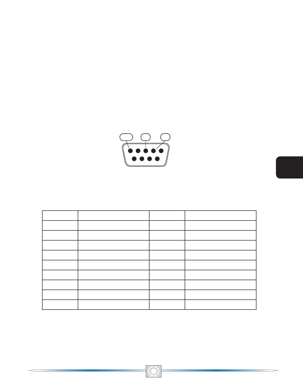
The RS-232 port on the rear panel uses a DB-9 female connector. Figure 4-4 Illustrates the pin assignments of
the communication port and Table 4-3 identies the RS-232 connector pin functions. A standard communication
cable terminated with a DB-9 male connector is used for PC or hand-held computer interface with the DVR2000E
as shown in Figure 4-5.
Figure 4-4. Communication Port Pin Assignments
Table 4-2. Communication Port Pin Functions
Pin Function Name Direction
1 N/C ---- N/A
2 Transmit Data TXD From DVR2000E
3 Receive Data RXD To DVR2000E
4 N/C ---- N/A
5 Signal Ground GND N/A
6 N/C ---- N/A
7 N/C ---- N/A
8 N/C ---- N/A
9 N/C ---- N/A
30
3
Main Index
5
Section 4 Index
31
3
Main Index
5
Section 4 Index