S
ection
3
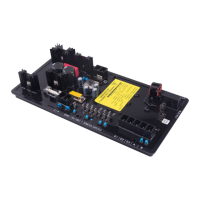
Front Panel Switches
Changes to settings can be made at the front panel using the three pushbutton switches. These push-buttons are
labeled Select, Up, and Down. Section 2, Human-Machine Interface provides more in-formation about the front
panel switches.
Relay Output
A common alarm output contact is provided through terminals AL1 and AL2. This normally open, form A contact
annunciates alarm or generator trip conditions and closes in the event of a protective shutdown or transfer. The
relay output is non-latching.
DVR2000E OPERATING FEATURES
The following paragraphs describe the characteristics of each DVR2000E operating feature.
Operating Modes
The DVR2000E provides up to four modes of operation selectable through Windows® or Palm OS® communication
software. Automatic voltage regulation mode and Manual mode are standard features. Var and Power Factor
modes are an option.
Automatic Voltage Regulation Mode
In Automatic Voltage Regulation (AVR) mode, the DVR2000E regulates rms generator output voltage. This is
accomplished by sensing generator output voltage and adjusting dc output excitation current to maintain voltage
at the regulation setpoint. The regulation setpoint is adjusted by the Raise and Lower contact inputs, front panel
switches, or through Windows® or Palm OS® communication software. The regulation point may also be modied
by the Droop function or the Underfrequency function under certain conditions.
Manual Mode
In Manual mode, also known as Field Current Regulation (FCR) mode, the DVR2000E maintains dc excitation
current at a set level. The current-level setpoint is adjustable from 0 to 3 Adc by the Raise and Lower contact
inputs, front panel switches, or through Windows® or Palm OS® communication software.
WARNING!
The Manual mode excitation level must be evaluated prior to enabling this feature. If the level of
excitation current is inappropriate for the generator, severe damage to the generator may occur.
For initial startup, if the regulator is in Manual mode and set at 0.25 amperes, the generator should come up to
approximately half-voltage. This allows wiring and sensing leads to be checked before the regulator is switched to
AVR mode. Increasing the eld current to 0.5 amperes will bring the generator up to approximately rated, no-load
voltage.
Var Control Mode (Optional)
In Var Control mode, the DVR2000E(C) maintains generator vars (volt-amperes, reactive) at a set level when
paralleling with an innite bus. The DVR2000E(C) calculates generator vars using the sensed generator output
voltage and current quantities and then adjusts the dc excitation current to maintain vars at the setpoint. Var control
is enabled and disabled through the front panel switches, Windows® or Palm OS® communication software.
When the software is turned on, var control is enabled or disabled through the Var/Power Factor Control (52J/K)
contact input circuit. The var setpoint is adjustable from 100 percent absorb to 100 percent generate through the
Raise and Lower contact inputs, front panel switches, or through Windows® or Palm OS® software.
Power Factor Control Mode (Optional)
In Power Factor Control mode, the DVR2000E(C) maintains generator power factor at a set level when paralleling
20
3
Main Index
5
Section 3 Index
21
3
Main Index
5
Section 3 Index