S
ection
6
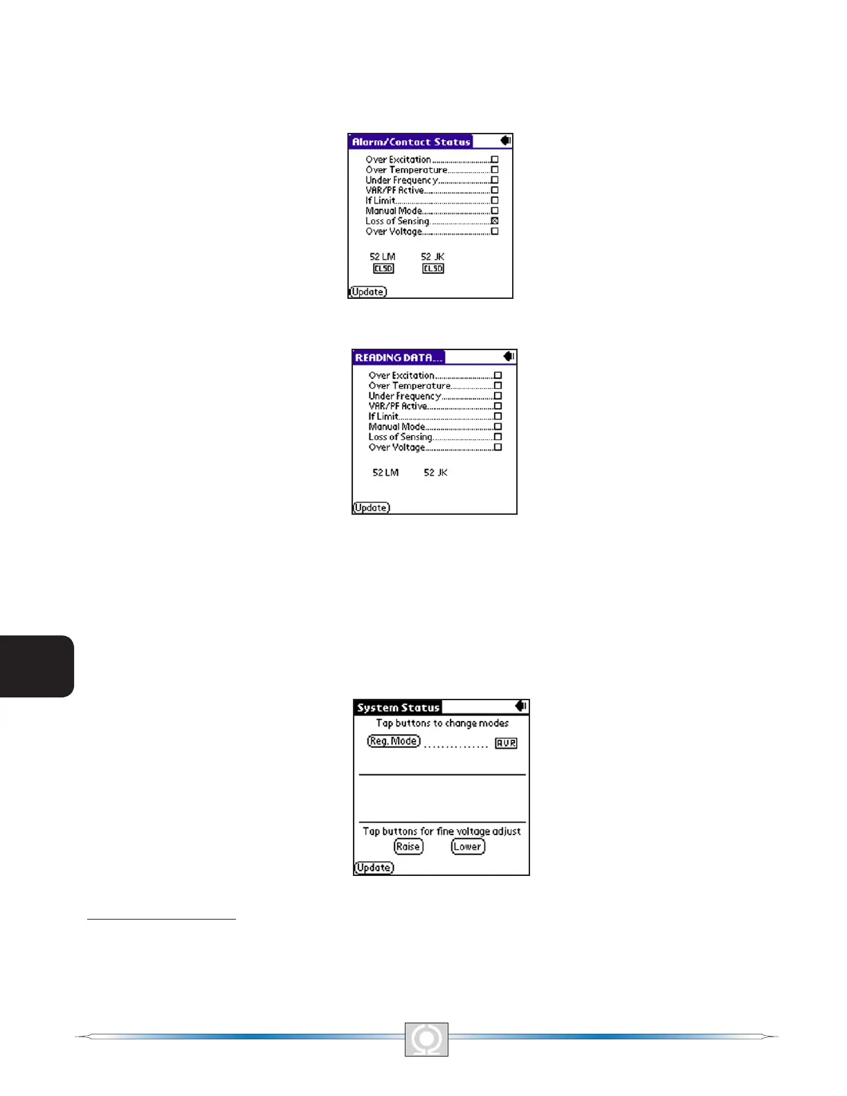
Figure 6-20 (Alarm/Contact Status Screen) shows how the screen appears after all polling is complete. The screen
displays the status of the DVR2000E front panel LEDs. An alarm condition is indicated by a checked box (x).
The screen also indicates the position of the DVR2000E 52 LM, and 52 JK contact inputs. To refresh the status of
the Alarm/Contact Status indicators, tap the Update button. To return to the Main Screen, tap the Back icon 3).
Figure 6-20.Alarm/contact Status Screen
Figure 6-21.Reading Data Screen
System Status
The System Status Without Operating Mode Screen shown in Figure 6-22 is accessed from the Main Screen
(Figure 6-14) by tapping the arrow on the Other Pages: line and then tapping System Status. The System Status
Screen displays the current mode setting.
Figure 6-22. System Status Without Operating Mode Screen
Regulation Mode Button
Tapping the Reg. Mode button toggles between Field Current Regulation (FCR) mode and Automatic Voltage
Regulation (AVR) mode.
80
3
Main Index
5
Section 6 Index
81
3
Main Index
5
Section 6 Index