S
ection
6
Operating Mode Buttons
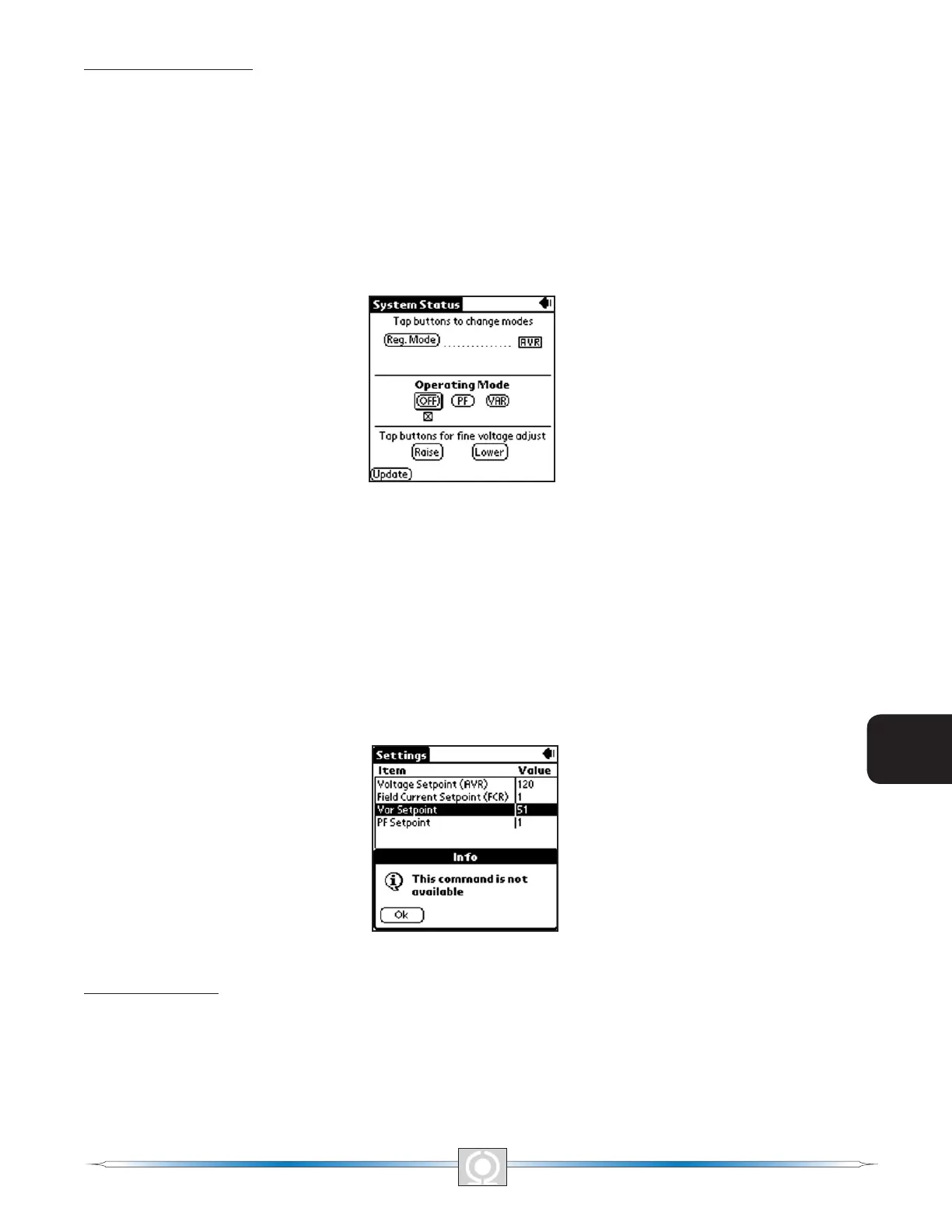
If the Var/PF option is installed, the Systems Status Screen may be different than that of Figure 6-22. This is
illustrated in Figure 6-23, System Status With Operating Mode Screen. The Operating Mode segment of the System
Status Screen (Figure 6-23) has three buttons labeled OFF, PF and VAR. A box around the Operating Mode’s
OFF, PF and VAR buttons indicates which mode is selected. A checked box below the buttons indicate which of
the three modes the DVR2000E is currently operating in. The gure also shows that the selected operating mode
is VAR while the DVR2000E is operating in OFF (AVR mode). Tapping the PF button places the DVR2000E in the
power factor operating mode and causes a checked box (x) to appear below the PF button. Tapping the VAR
button places the DVR2000E(C) in the VAR operating mode and causes a checked box to appear below the VAR
button. Tapping the OFF button disables both power factor and var regulation and places a checked box below the
OFF button. The example of Figure 6-23 shows that power factor and var regulation are disabled.
Figure 6-23. System Status With Operating Mode Screen
Operation of the Operating Mode controls is determined by the status of the contacts connected across the
DVR2000E(C) Var/PF Control terminals (52J, 52K). When these contacts are open, the Operating Status controls
are enabled. Closing the contacts at terminals 52J and 52K disables the Operating Status controls and interrupts
regulation of vars or power factor until the contacts are opened again.
If a setting change is attempted and the requested feature or capability is not installed, then This command is not
available message will be displayed after tapping the Update button. Figure 6-24, Command Not Available Screen
illustrates this event. Tap OK to return to the previous screen.
Figure 6-24. Command Not Available Screen
Fine Adjust Buttons
Fine adjustments to the operating setpoint are made by tapping the Raise and Lower buttons of the System Status
Without Operating Mode Screen (Figure 6-22). (The ne adjustment through the front panel push buttons only
controls the voltage setpoint.) An arrow serves as a reminder of which button was last tapped. In AVR mode, a
single tap of the Raise or Lower buttons increments or decrements the generator voltage by 0.1 volts and the
range of which is constrained by the Generator Rated Voltage and the Generator Voltage Adjust Band settings. For
80
3
Main Index
5
Section 6 Index
81
3
Main Index
5
Section 6 Index