S
ection
5
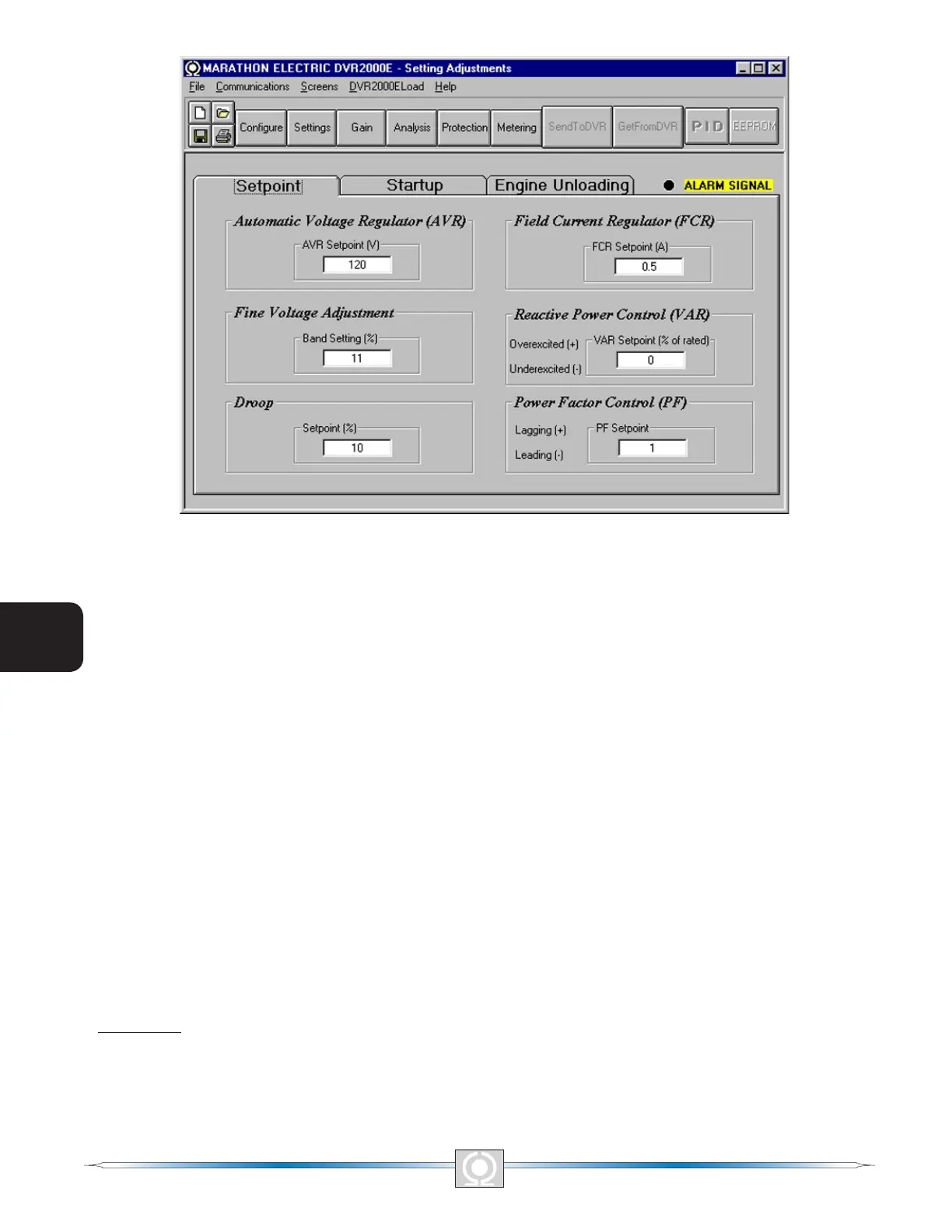
Figure 5-9. Setting Adjustments Screen, Setpoint Tab
Automatic Voltage Regulator (AVR) - AVR Setpoint (V). This setting eld is used to enter the desired generator
output terminal voltage. The AVR setpoint value range depends on the regulator sensing voltage and band
setting.
Fine Voltage Adjustment - Band Setting (%). The Band Setting determines the minimum and maximum adjustment
allowed to the AVR Setpoint. This value is expressed as a percentage of the Regulator Sensing Voltage (see
Figure 5-8). Band Setting values are entered as a percentage over a range of 0 to 15 percent in 0.1 percent
increments.
Droop - Setpoint (%). This setting controls the reactive droop compensation feature of the DVR2000E. The setpoint
value is based on a 0.8 power factor load and determines the amount of change permitted in the generator voltage
setpoint when the DVR2000E responds to a reactive load. The setpoint value is adjustable from 0 to 10 percent
in increments of 0.01 percent.
Field Current Regulator (FCR) - FCR Setpoint (A). This setting denes the eld current setpoint when operating
in Manual mode. The FCR Setpoint eld accepts a value of 0 to 3 Adc in increments of 0.01 Adc
Reactive Power Control (VAR) - VAR Setpoint (% of nom.). The VAR Setpoint determines the level of generator
vars maintained by the DVR2000E when operating in Var Control mode. Values from -100 to +100 percent in 1.0
percent increments may be entered in the VAR Setpoint eld.
Power Factor Control (PF) - PF Setpoint. The PF Setpoint determines the level of generator power factor
maintained by the DVR2000E when operating in Power Factor Control mode. PF Setpoint values are adjustable
from -0.6 to -1 (1) or 0.6 to +1 in 0.001 increments.
Startup Tab
The Startup-tab settings of the Setting Adjustment screen are shown in Figure 5-10. Each setting of the Startup
tab is described in the following paragraphs.
46
3
Main Index
5
Section 5 Index
47
3
Main Index
5
Section 5 Index