Chapter 2
Periodic maintenance
Section 2 Maintenance and adjustment
2
—
4
Section 2 Maintenance and adjustment
This section describes the service procedure for each
section of the periodic maintenance
VALVE CLEARANCE
In the first 1000km (5 months) and every 4000km
(20 months) thereafter, it should carry out the
inspections.
Inspect
Remove the saddle
Remove the fuel tank
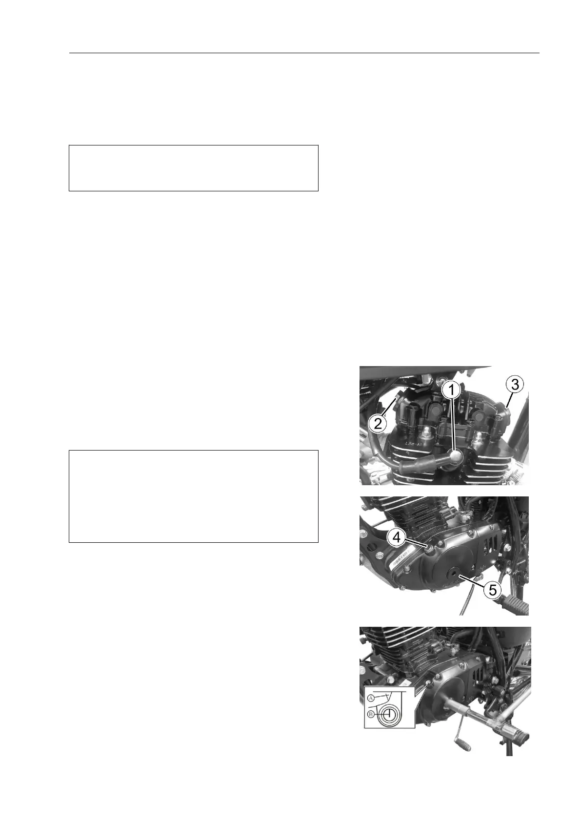
Remove the spark plug①.
Remove the valve inspection cover② and ③.As fig
2.2.1.
The valve clearance specifications of the intake valve
and exhaust valve are different. It needs to check and adjust
the valve clearance in the following conditions:
1) Regular maintenance;
2) Valve mechanism maintenance;
3) Maintenance when removing the camshaft
Valve clearance (when cold)
Intake:0.06—0.08mm
Exhaust:0.10—0.12mm
Note:
When checking or adjusting the valve clearance,
the piston must be at the top dead center (TDC) of
the compression stroke.
The valve clearance can only be checked when
the engine is cold.
Remove the valve timing screw plug④and magneto
plug ⑤. Fig.2.2.2.
Use the socket wrench to turn the camshaft
counterclockwise, when the intake rocker arm drops and
rises, the piston reaches the top dead center (TDC) of the
compression stroke. (Rotate the crankshaft until the mark B
on the magneto rotor is aligned with the triangle mark A on
the magneto cover).
Fig.2.2.3.
Insert the feeler gauge into the gap between the valve
lifter and adjustment screw on the rocker arm.
If the gap exceeds the specifications, it should be
adjusted according to the following requirements.
As in Fig.2.2.4.
Adjustment
Use a screwdriver and a socket
off-set wrench to adjust the gap.
Loosen the lock nut ⑥.
Insert the feeler gauge into the gap
between the valve stem and adjustment
screw on the rocker arm.
Adjust the valve clearance by
turning the adjustment screw ⑦, while
fixing the lock nut ⑥. As in Fig.2.2.5.
After the adjustment, tighten the
lock nut.
Use the socket off-set wrench to
rotate the crankshaft 720°,and check
whether the gap is within the specified
range.
Fig 2.2.1
Fig2.2.2
Fig 2.2.3