Chapter 3 Engine Section 4 Inspection and maintenance of engine componenets
3—21
Cylinder cranium
As in Fig.3.4.10
Note:
Mark the position of each removed component.
The components shall be placed in groups (i.e.,
intake or exhaust) so that they can be assembled in
place.
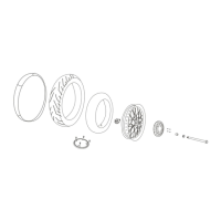
Remove
Remove valve inspection hole cap , .① ③
As Fig. 3.4.10
Remove rocker arm shaft bolts②.
Remove rocker arm shaft④
Remove the rocker arm⑤and waveform washer ⑥).
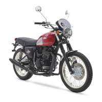
As in Fig.3.4.11
Cylinder head cover deformation
After removing the sealant from the mating surface of the
cylinder head cover, place the cylinder head cover on a flat
plate and check for deformation with a feeler gauge.
Check each point according to the diagram.
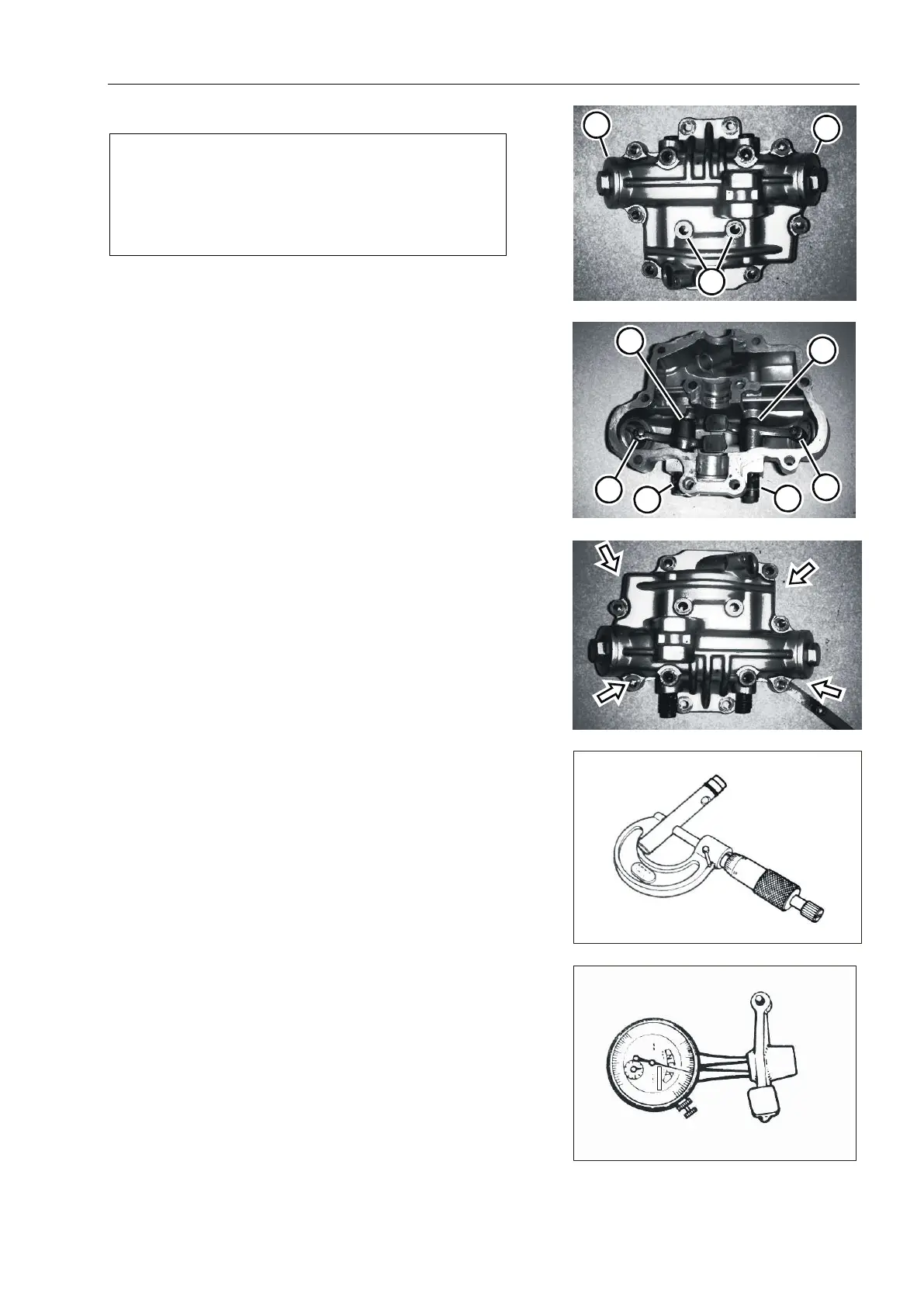
As Fig. 3.4.12
Tools: feeler gauge Limit of use: 0.05mm
If the deformation exceeds the limit, replace the cylinder
head.
Outer diameter of rocker arm shaft (O, D)
Measure rocker shaft diameter.
As Fig. 3.4.13
Tools: micrometer calipers (0 -- 25 mm)
Standard: 11.979 -- 11.990 mm
Inner diameter of rocker arm (1, D)
Measure the inner diameter of rocker arm and check the
wear of camshaft contact surface.
As Fig. 3.4.14
Standard: 12.000-12.018 mm
Fig.3.4.10
1
Fig.3.4.11
5
4
4
6
Fig.3.4.12
Fig.3.4.13
Fig.3.4.14