Chapter 3 Engine Section 5 Engine reassembly
3—55
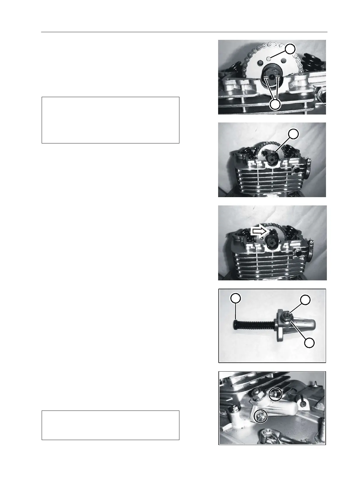
Adjust the line mark on the camshaft to make it
parallel to the matching surface of the cylinder head and ①
cylinder head cover.
The sprocket, chain and camshaft are assembled so
that the locating pin holes on the sprocket engage exactly ②
at the position shown.
As in Fig.3.5.61
Note:
Do not turn the crankshaft when installing
the camshaft or chain.
Apply a small amount of thread sealant to
the threads of camshaft sprocket bolts.
Install gasket to cover the locating pin.③
Tighten camshaft sprocket bolts with specified torque.
Camshaft sprocket bolts: 11 n · m (1.1 kg · m)
As in Fig.3.5.62
Bend the gasket steadily.
As in Fig.3.5.63
CAM CHAIN TENSION ADJUSTER
Follow the steps below to install the chain tension
adjuster.After loosening the nut ④, loosen the positioning
screw ⑤ 1 turn, and then completely insert the push rod ⑥
into the regulator, and lock the push rod by tightening the
positioning screw.
As in Fig.3.5.64
Attach the chain tension adjuster to the cylinder and
tighten the mounting bolt for the specified torque.
As Fig. 3.5.65
Chain tensioner mounting bolt: 7 n·m (0.7 kg·m)
Note:
Replace with new gaskets.
Fig.3.5.61
1
Fig.3.5.62
Fig.3.5.63
Fig.3.5.64
4
5
6
Fig.3.5.65