CRIMP DATA ANALYZER
CDA10
REV.01
5.2.1.2 STANDARD
The operations to be carried out to connect the load cell electrically are:
• Check that the switch, located on the press or in the electrical cabinet/panel, is in the OFF (O)
position.
• Disconnect the press from the electrical mains.
• Open the electrical box of the press.
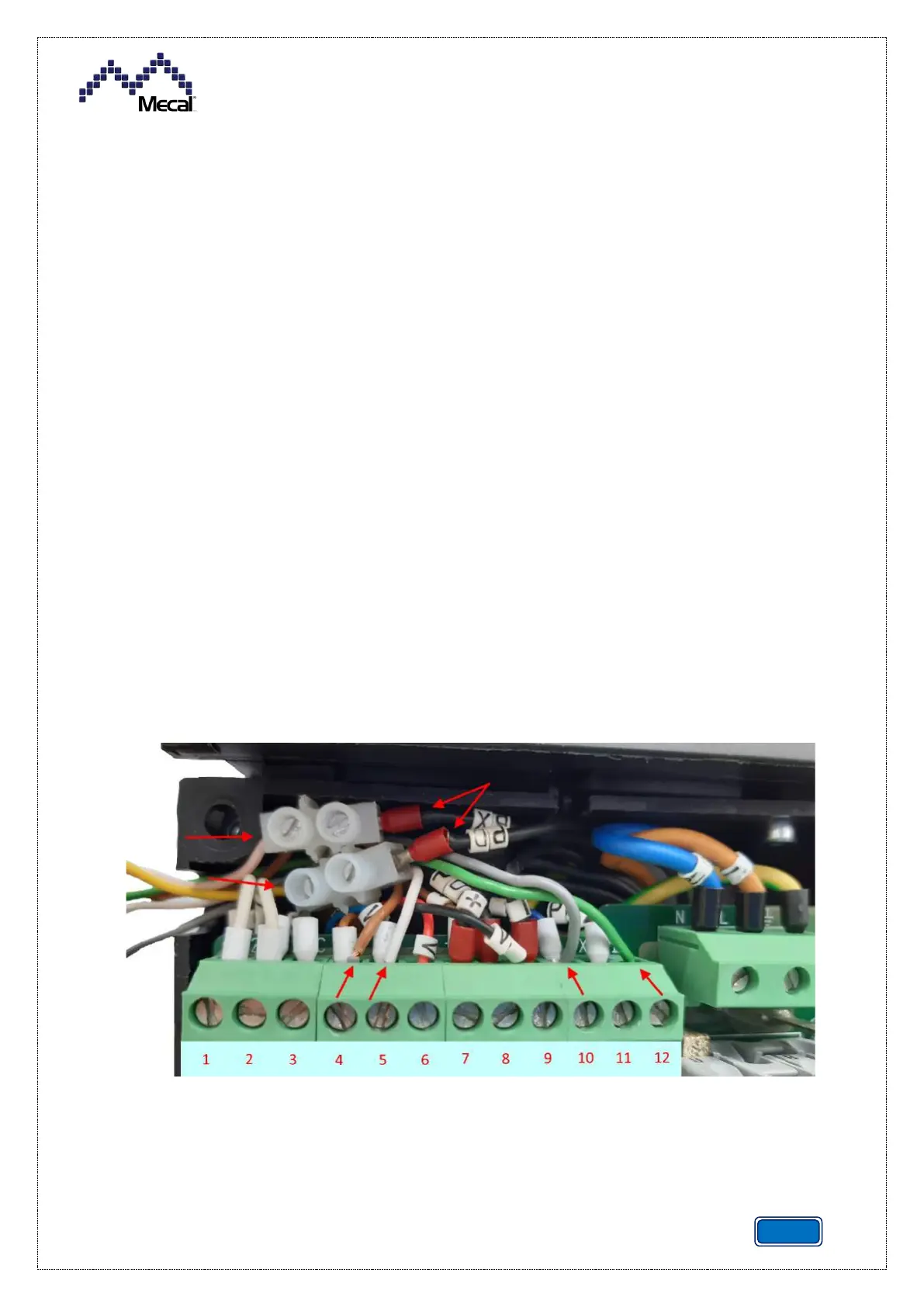
• Intercept the cables from the load cell and BCC: white, brown, yellow, green, rose and grey.
• Connect the brown cable to the pos.4 input [+18V] on the terminal board (combined with the
cable present).
• Connect the white cable to the pos.5 input on the terminal board (combined with the cable
present).
• Connect the grey cable to the pos.10 input on the terminal board (combined with the cable
present).
• Connect the green cable to the pos.12 input on the terminal board (combined with the cable
present).
• Connect the yellow cable to the black cable with PD indication by means of the supplied clamp.
• Connect the rose cable to the black cable with PX indication by means of the supplied clamp.
• Close the electrical box with the screws.
• Connect the press to the electrical mains.
• Move the switch to the ON (I) position.
• Configure the load cell [see the relative paragraph].