CRIMP DATA ANALYZER
CDA10
REV.01
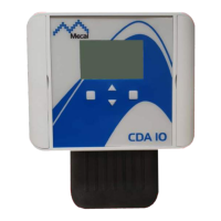
• Connect the yellow cable to the pos.6 input on the terminal board;
• Connect the green cable to the pos.7 input on the terminal board;
• Close the door on the electrical box;
• Connect the press to the electrical mains;
• Move the switch to the ON (I) position;
• Configure the load cell [see the relative paragraph].
5.2.4 REPLACING THE FORCE CELL TT1000 WITH CDA10
The operations to be carried out to replace load cell TT1000 with load cell CDA10 are:
• Check that the switch, located on the press or in the electrical cabinet/panel, is in the OFF (O)
position;
• Disconnect the press from the electrical mains;
• Disassemble cell TT1000 to be replaced, disconnecting it from all connectors;
• The load cell sensor does not need to be disassembled (if working);
• The encoder does not need to be disassembled (if working);
• Install the new sensing unit on its support [see relative paragraph];
• Connect the load cell sensor to the relative input;
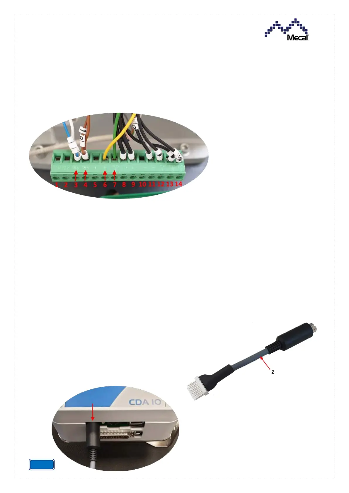
• Connect the encoder to the load cell sensing unit
using the supplied adapter (Z);
• Connect the cables from the sensing unit to the
press, following the paragraph on connection
referring to the corresponding press model;
• The new load cell must be configured [see relative
paragraph].