2B-16 - ELECTRICAL 90-826148R2 MARCH 1997
Brush Replacement
IMPORTANT: Replace brushes that are pitted or
worn to less than 1/4 in. (6.4mm) in length
.
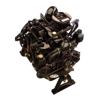
1. Install positive brushes into commutator end cap.
11660
a
b
c
d
e
f
g
a - Positive (+) Terminal
b - Long Brush Lead
c - Push Lead Into Slot
d - Insulating Washer
e - Flat Washer
f - Lock Washer
g - Nut
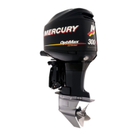
2. Install components.
11656
a
b
c
d
d
a
b
a - Positive (+) Brushes
b - Negative (–) Brushes
c - Brush Holder
d - Bolts (Fasten Negative Brushes and Holder)
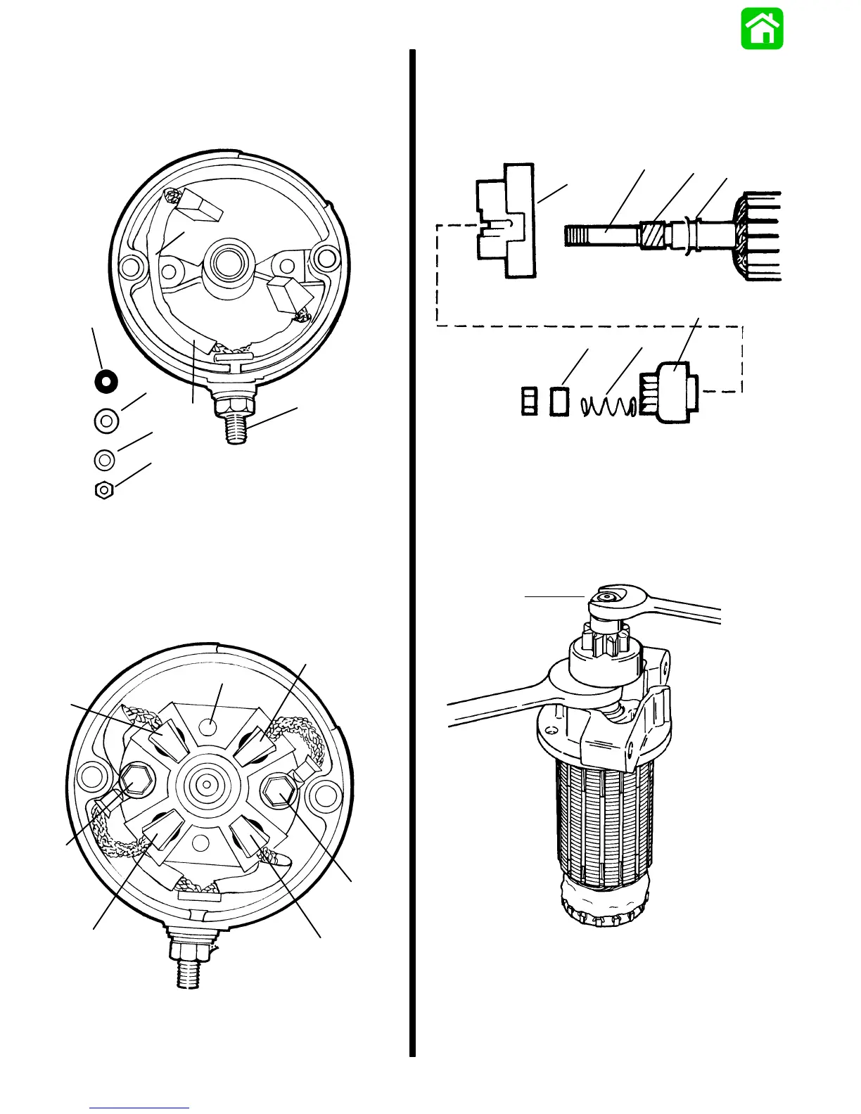
Reassembly
1. Lubricate helix threads and drive end cap bush-
ing with SAE 10W oil.
2. Install components onto armature shaft.
11658
a
b
c
d
e
f
g
a - Washer
b - Helix Threads
c - Armature Shaft
d - Drive End Cap
e - Drive Assembly
f - Spring
g - Spacer
3. Install locknut.
51711
a
a - Locknut

 Loading...