ELECTRICAL - 2B-1790-826148R2 MARCH 1997
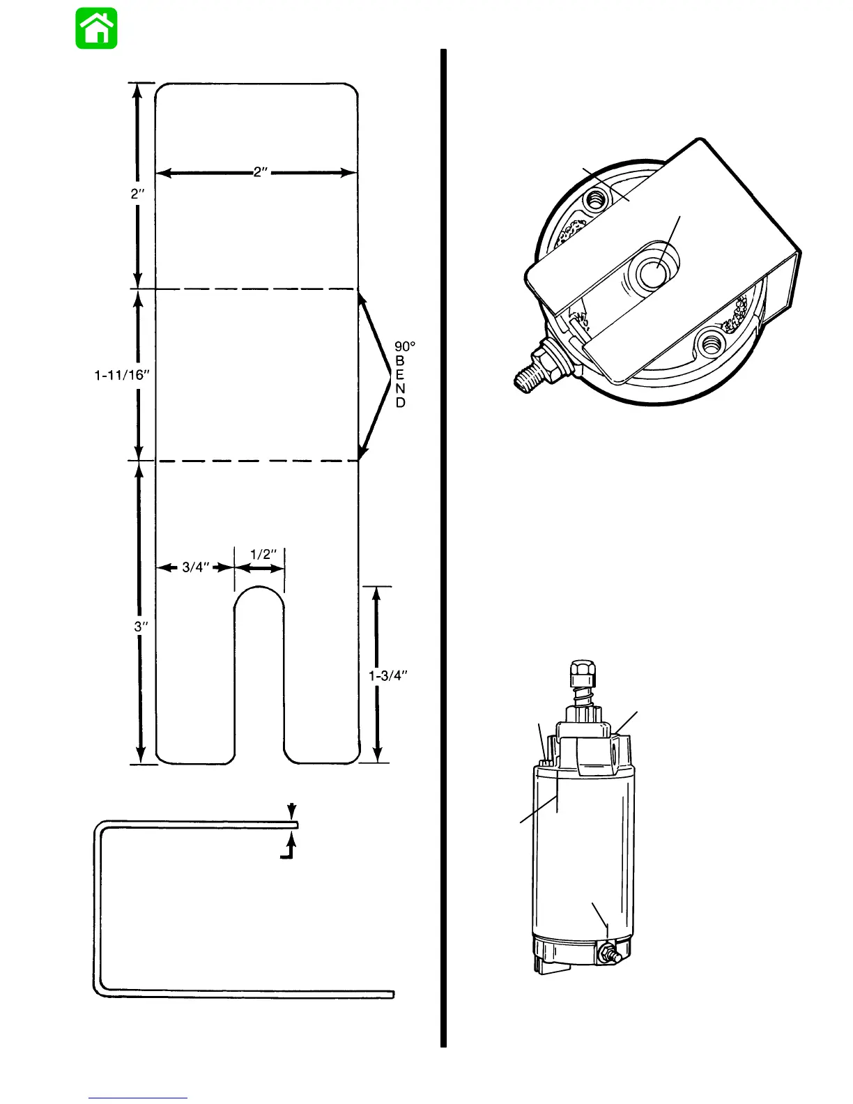
4. Construct a brush retainer tool as shown.
Brush Retainer Tool Layout (Full Size)
18-Gauge Sheet Metal
METRIC
SCALE
3”
2”
1-3/4”
1-11/16”
3/4”
1/2”
= 76.2mm
= 50.8mm
= 44.5mm
= 42.9mm
= 19.1mm
= 12.7mm
Brush Retainer Tool Side View (Full Size)
5. Place springs and brushes into brush holder and
hold in place with brush retainer tool.
6. Lubricate bushing with one drop of SAE 10W oil.
DO NOT over-lubricate.
11661
a
b
a - Brush Retainer Tool
b - Bushing
7. Position armature into starter frame so that com-
mutator end of armature is at end of starter frame
where permanent magnets are recessed 1 in.
(25.4mm). Align marks as shown.
8. Install commutator end cap onto starter frame;
align marks as shown, and remove brush retainer
tool.
9. Install thru bolts and torque to 70 lbs. in. (7.9
N·m).
52659
a
b
c
c
a - Alignment Marks
b - Alignment Marks
c - Bolt (2) Torque to 70 lb. in. (7.9 N⋅m)

 Loading...