ENGINE MECHANICAL
SERVICE MANUAL NUMBER 22
90-860074--1 FEBRUARY 2002 Page 3A-51
VALVE GUIDE REPLACEMENT
1. Remove valve stem seals.
2. Heat head in oven to 85 degrees C (185 degrees F). Using a suitable drift, drive out old guide
from underside of head.
CAUTION
To avoid distortion or melting of aluminum heads, Do NOT use a torch to replace
valve guides.
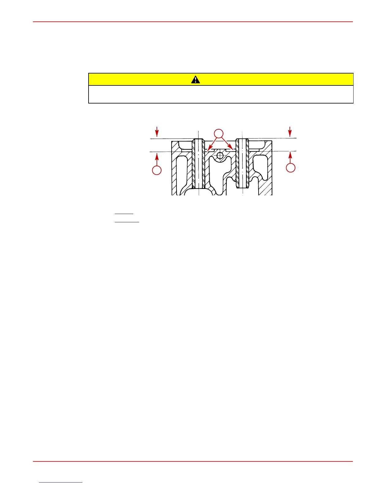
3. With head temperature at 85 degrees C (185 degrees F), press new guide in to obtain
measurement as shown.
a
b
c
a-Spring Seat Counterbore
b-Intake
Guide Height Measurement: 7.94 - 7.96 mm (.312 -.313 in.)
c-Exhaust
Guide Height Measurement: 7.92 -7.94 mm (.311 to .312 in.)
IMPORTANT: If the valve guide has been removed, both the valve and the valve guide
must be replaced as a set.
VALVE REFACING
Pitted valves can be refaced to proper angle on a valve grinder, thus insuring correct relation
between cylinder head seat and valve mating surface. Replace valves with excessive wear on
stems or valves which are warped excessively. When an excessively-warped valve head is
refaced, a knife edge will be ground on part or all of the valve head, due to amount of metal that
must be removed to completely reface. Knife edges lead to breakage or burning. After grinding,
measure valves and replace if out of specifications.
Various equipment is available for refacing valves. Manufacturer’s recommendations should be
carefully followed to attain proper results.
Refer to Specifications for valve specifications.
CYLINDER HEAD RESURFACING
The cylinder heads on these marine diesel engines are treated with a protective nickel
coating to resist corrosion and should not be resurfaced. Resurfacing would remove the
nickel coating. Do NOT resurface the cylinder heads.
 Loading...