EDI DIAGNOSIS SERVICE MANUAL NUMBER 22
Page 5E-16 90-860074--1 FEBRUARY 2002
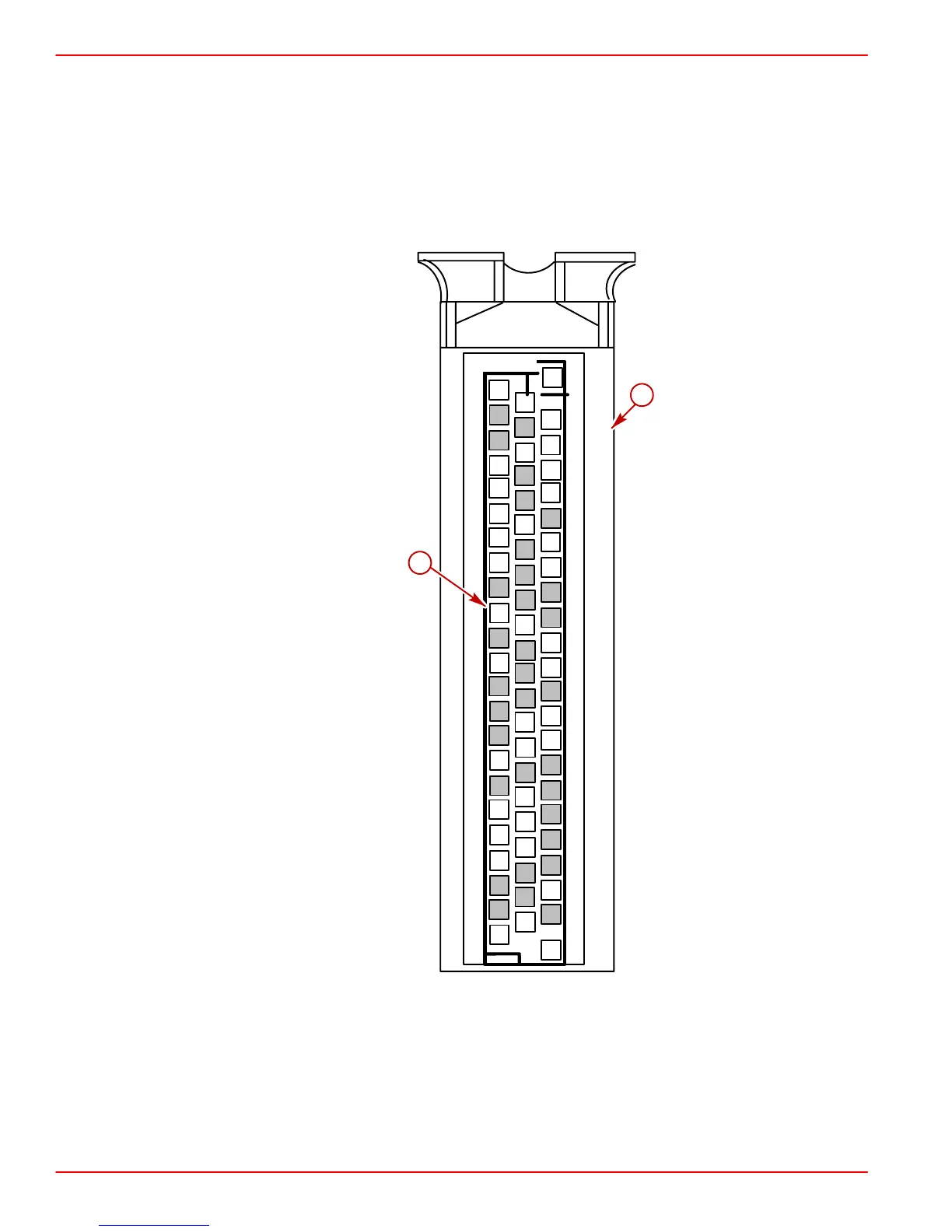
ECM Connector Pin Layout
All related wiring attaches to the ECM with one 68 pin wiring harness connector. This
connector is represented by the following diagram. The numbered squares represent a pin
and its relative location in the cavity of the ECM. Those numbered squares which appear
shaded represent pins not utilized in the Marine application. The white squares indicate pins
that are currently used and have corresponding wires connected when the harness is
attached to the ECM. Refer to Connector Chart for additional information.
1
2
7
8
3
4
5
6
9
10
15
16
11
12
13
14
18
19
17
20
22
21
24
29
30
25
26
27
28
31
32
37
38
33
34
35
36
40
41
39
42
44
45
43
46
47
52
53
48
49
50
51
54
55
60
61
56
57
58
59
63
64
62
65
67
68
66
2
1
22
23
68
46
23
a
b
a-ECM Wiring Harness Connector
b-Number And Location Of Individual Pin (68 Total)
 Loading...


