EDI DIAGNOSIS
SERVICE MANUAL NUMBER 22
90-860074--1 FEBRUARY 2002 Page 5E-17
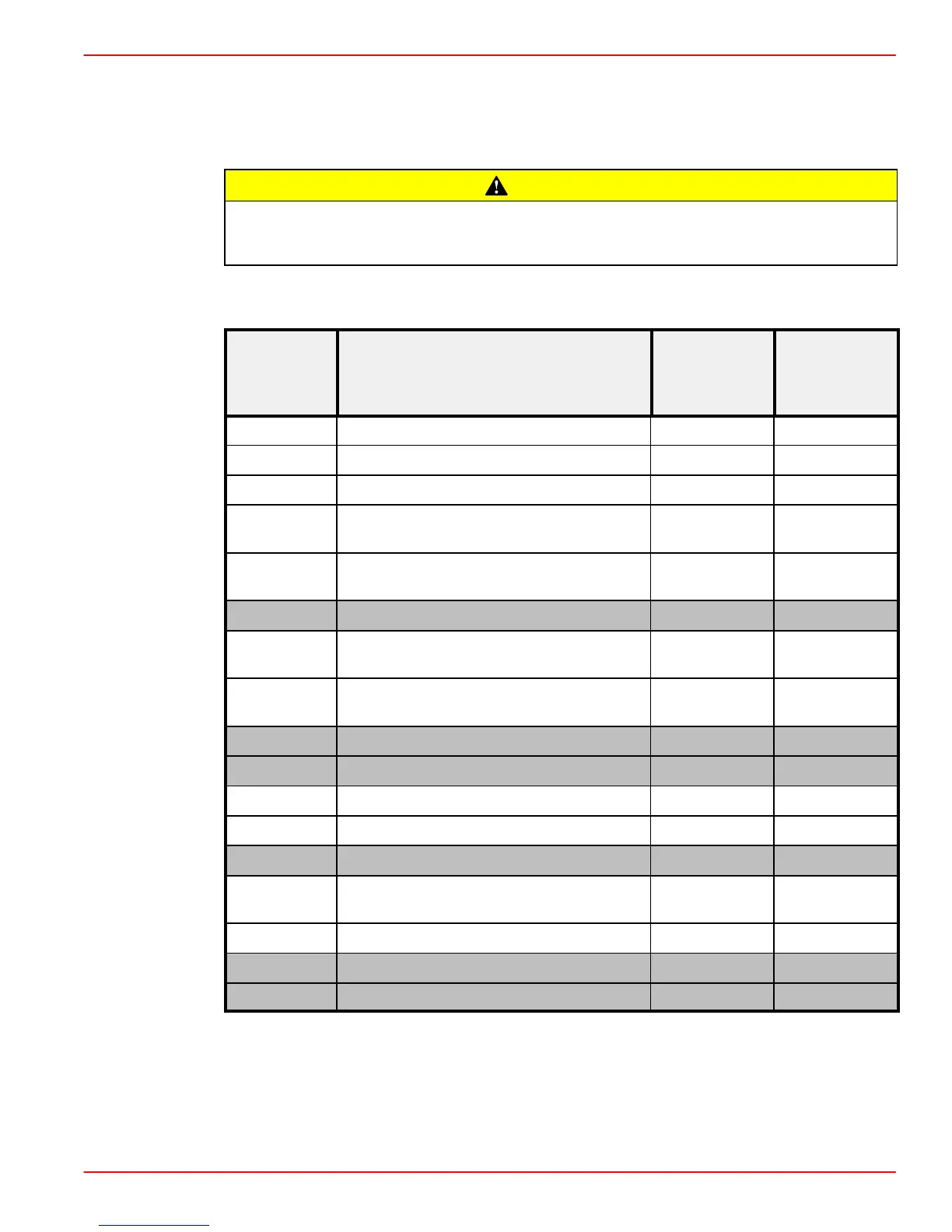
Connector Chart
The following chart will aid in identification and diagnosis of wiring circuits that are attached
to the ECM through the 68 pin connector.
CAUTION
AVOID loss of engine operation or wiring damage. Serious electrical damage could
result from improper probing of wires and connectors. Do NOT damage wires,
connectors or electrical system.
NOTE: Clear each code after disconnecting and reconnecting each sensor. Failure to do
so may result in an incorrect diagnosis of the problem.
Wire Color
Diagnostic
Trouble
ECM Pin Circuit Designation
Wire Color
Abbreviation
Trouble
Codes
ScanTool
1 Battery Minus BLK P1600
2 Engine Speed sensor signal output BRN/BLK P1735
3 Glowplug Indicator Lamp BLK/YEL P1645
4 Fuel Quantity Actuator
GRN/WHT
(twisted pair)
P1220
5 Fuel Quantity Actuator
GRN/WHT
(twisted pair)
P1220
6 Unused - -
7
Fuel Quantity Control Sleeve Position
Sensor (Middle Tap)
ORN P1225
8
Engine Speed Sensor Signal (shield
wire)
WHT P0725
9 Unused - -
10 Unused - -
11 Instrumented Injector Ground BRN P1201
12 Instrumented Injector Signal WHT P1725
13 Unused - -
14
Engine Coolant Temperature (ECT)
Sensor
WHT/BRN P0115
15 Throttle Position Sensor (signal) ORN/WHT P1515
16 Unused - -
17 Unused - -
 Loading...