EDI DIAGNOSIS SERVICE MANUAL NUMBER 22
Page 5E-18 90-860074--1 FEBRUARY 2002
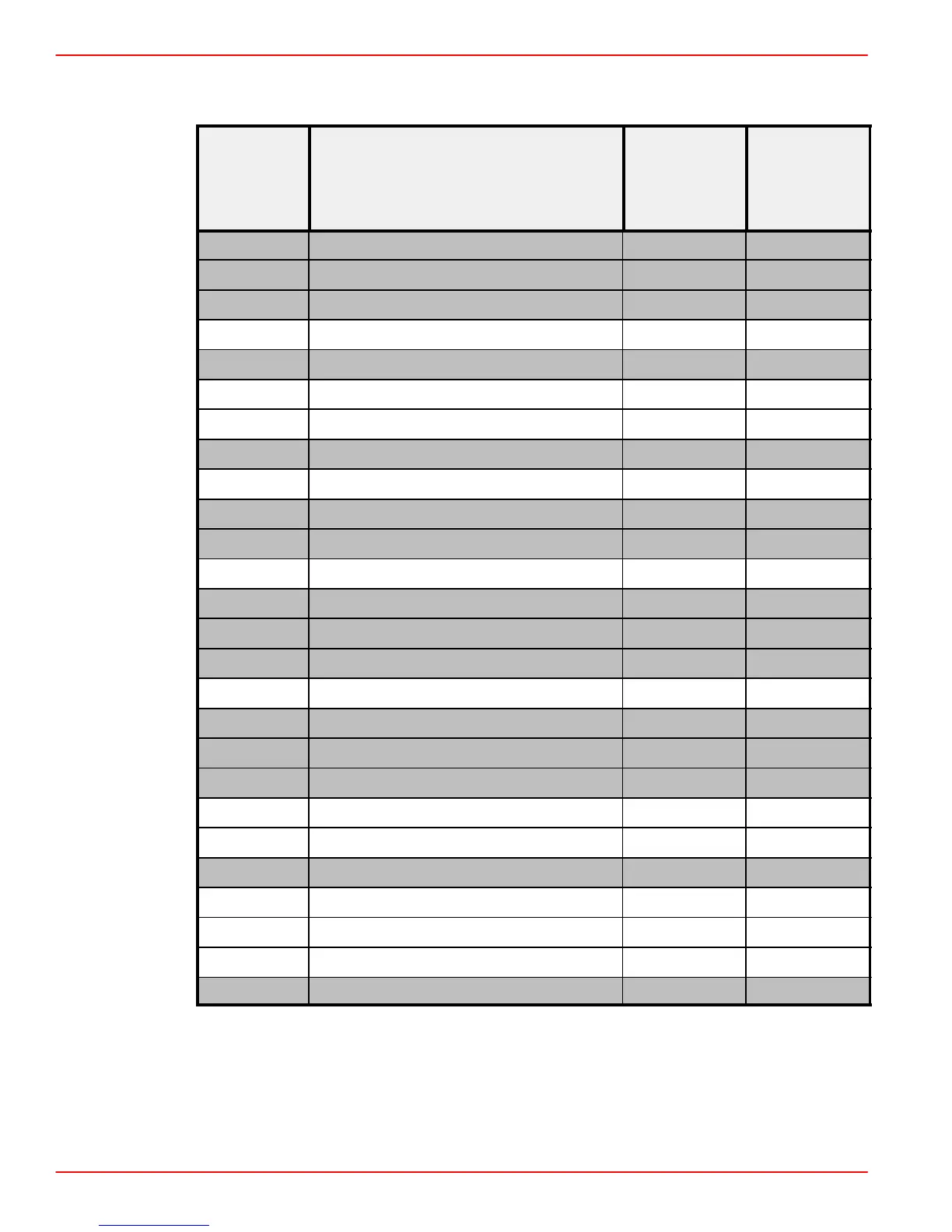
Connector Chart (continued)
Wire Color
Diagnostic
Trouble
ECM Pin Circuit Designation
Wire Color
Abbreviation
Codes
DTC(s)
ScanTool
18 Unused - -
19 Unused - -
20 Unused - -
21 Engine Speed Sensor (Digital) BRN/RED P0725
22 Unused - -
23 Battery Feed RED P1600
24 Battery Minus BLK P1600
25 Unused - -
26 Malfunction Indicator Lamp (MIL) BRN/WHT P1650
27 Unused - -
28 Unused - -
29 Control Sleeve Position Sensor GRN P1225
30 Unused - -
31 Unused - -
32 Unused - -
33 Analog Ground (ECT / Injection Pump) BRN/PUR P0115
34 Unused - -
35 Unused - -
36 Unused - -
37
1
Idle rpm Increase Signal RED/ORN -
38 Switched battery (15 - Ignition) PNK P1605
39 Unused - -
40 MAP Sensor Signal WHT/YEL P0105
41 5 Volt Output GRN
42 Main Relay WHT/RED P1625
43 Unused - -
1
: Unused on early model engines with 11 Pin ECM harness connector at electrical box.
 Loading...


