INSTRUMENTATION
SERVICE MANUAL NUMBER 22
90-860074--1 FEBRUARY 2002 Page 4D-25
NOTICE
Read WARNING about switch and sender testing in Precautions at front of this section
before proceeding with tests.
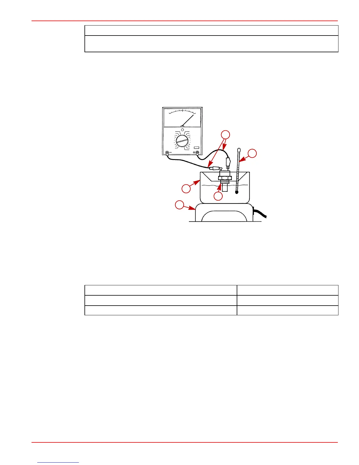
3. With an ohmmeter connected as in Step 1., use a suitable container, thermometer and
heat source and suspend sender with tip in sand.
4. Heat sand and observe thermometer.
5. As temperature rises, switch will close and ohmmeter will indicate continuity. Refer to
chart below for specifications.
72772
a
b
c
d
e
a-Suitable Container
b-Thermometer
c-Heat Source
d-Transmission Fluid Temperature Switch
e-Ohmmeter Leads
f-Audio Warning Buzzer With Jumper Lead
Test Temperature Switch Condition
126 - 138 Degrees C (258 - 282 Degrees F.) Closed
103 - 117 Degrees C (218 - 242 Degrees F.) Open
6. Turn heat source off. Allow sand to cool. Note thermometer reading to ensure switch
opens at specified temperature while cooling.
7. Replace switch if switch fails to either open or close within the specified temperature.
INSTALLATION
1. Apply Perfect Seal to threads of switch.
2. Install switch and sealing washer in transmission. Tighten securely.
3. Reconnect harness wires and coat with liquid neoprene.
4. Check transmission fluid level.
 Loading...