EDI DIAGNOSIS
SERVICE MANUAL NUMBER 22
90-860074--1 FEBRUARY 2002 Page 5E-31
TEST DESCRIPTION:
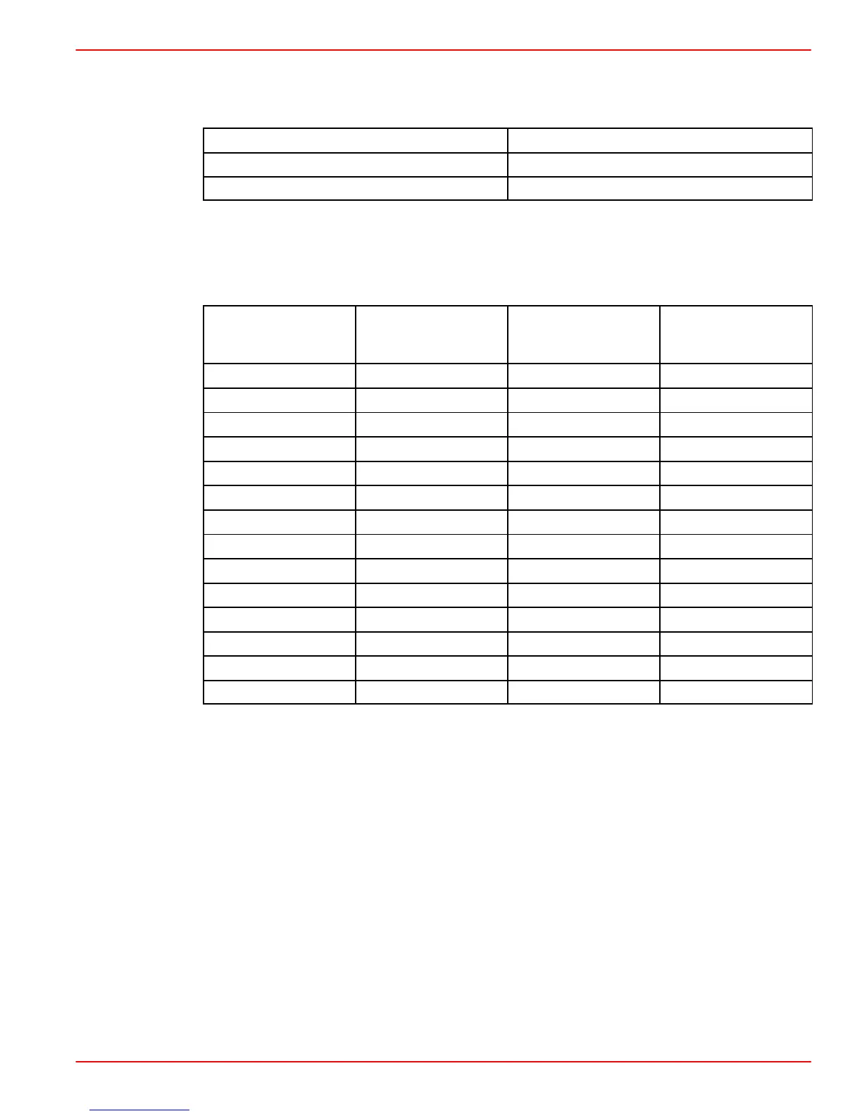
Verify continuity between the following pins:
ECM 68 PIN CONNECTOR
4 TERMINAL CONNECTOR AT MAP
55 1
64 2
Verify the sensor resistance between the two IAT sensor terminals as a function of
temperature:
NOTE: Stabilization time before each measurement should be at least 10 minutes in test
medium.
TEMPERATURE
°F (°C)
MINIMUM RESIS-
TANCE
(kOhm)
TYPICAL RESIS-
TANCE
(kOhm)
MAXIMUM RESIS-
TANCE (kOhm)
–40 (–40) 1 39.18 48.55 57.92
–30 (–23) 1 22.22 27.00 31.78
–20 (–5) 1 13.24 15.67 18.10
–10 (14) 1 8.160 9.45 10.74
0 (32) 1 5.180 5.89 6.60
10 (50) 1 3.390 3.79 4.190
20 (67) 1 2.270 2.500 2.730
30 (85) 1 1.528 1.692 1.856
40 (104) 1 1.059 1.170 1.281
50 (122) 1 0.748 0.826 0.904
60 (140) 1 0.538 0.594 0.650
80 (175) 1 0.2902 0.3224 0.3546
100 (212) 1 0.1641 0.1852 0.2063
120 (247) 1 0.0970 0.1116 0.1262
DIAGNOSTIC HELP:
Verify the following:
• Open or short in the CKT Pin 55 or CKT Pin 64.
• Bent pin at the ECT or ECM.
• Defective ECT or ECM.
IAT failure influences engine performance as follows:
• FUEL QUANTITY ACTUATION: Maximum engine rpm is 90% of the normal
operating range (15% of fuel quantity reduction).
NOTE: Failure of the IAT and MAP sensor at the same time will limit engine performance
to 60% maximum of the normal operating range (50% fuel quantity reduction).
IMPORTANT: Replace the O-ring seal whenever removing the IAT/MAP sensor.
Torque the sensor to specification when replacing.

 Loading...


