EDI DIAGNOSIS
SERVICE MANUAL NUMBER 22
90-860074--1 FEBRUARY 2002 Page 5E-53
TEST DESCRIPTION
NOTE: The relay terminal numbers can be found on the bottom of the relay.
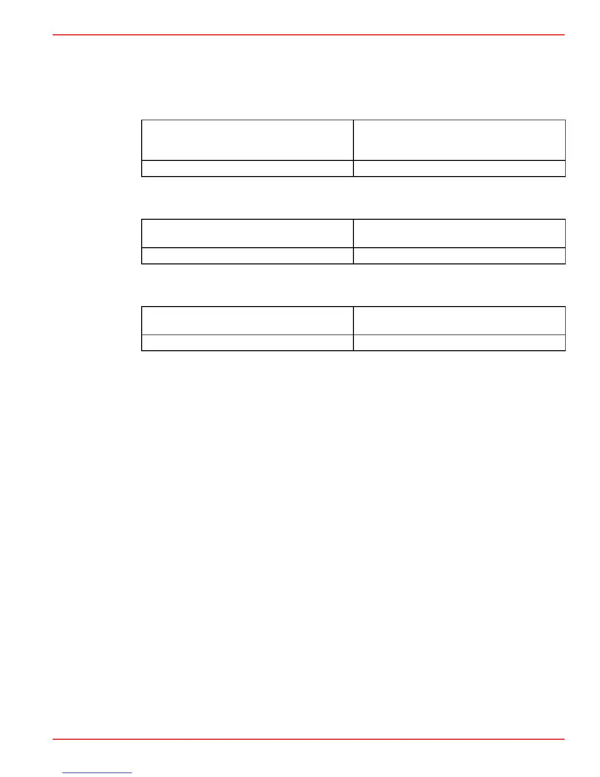
Verify continuity between the following with relay connectors unplugged and key OFF.
Measure:
GLOW PLUG RELAY CONNECTOR /
TERMINAL NUMBER
GLOW PLUG AUXILIARY RELAY CON-
NECTOR /
TERMINAL NUMBER
87 86
Verify supply voltage from circuit breaker to Glow Plug Auxiliary Relay with relay connector
unplugged and key ON. Measure:
CURRENT (VOLTS)
GLOW PLUG AUXILIARY RELAY CON-
NECTOR NUMBER
12 30
Verify supply voltage from Glow Plug Relay Actuator with relay connector unplugged and
key ON. Measure:
CURRENT (VOLTS)
GLOW PLUG AUXILIARY RELAY CON-
NECTOR NUMBER
12 86
DIAGNOSTIC HELP:
Verify the following:
• Open or short in wiring between glow plug relays.
• Improper terminals or pins at the electrical box, relay connectors or ECM.
• Defective circuit breaker.
• Defective Glow Plug Relay Actuator and/or Glow Plug Auxiliary Relay.
• Defective ECM.
Failure of the Glow Plug Auxiliary Relay influences engine performance as follows:
• Difficult or no starting.
• May have white smoke on start up.
 Loading...


