12-20 Probes and Biopsy
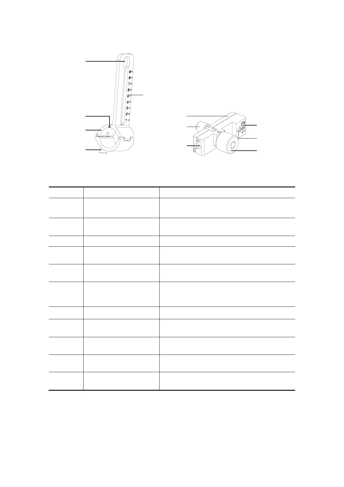
NGB-009
5
1
2
3
4
10
6
7
8
9
11
No. Name Description
<1>
Support of
needle-guided bracket
Used for installing the needle-guided bracket on
the transducer.
<2>
Knob of fixing
needle-guided bracket
Used for fixing the needle-guided bracket on the
transducer.
<3> Groove Match with the tab on the transducer.
<4>
Hole for installing guiding
block
Used for installing the knob of fixing
needle-guided bracket.
<5> Needle distance scales
Indicate distance between needle and the
transducer head surface.
<6> Guiding block
Used for installing biopsy needle; there are five
specifications of guiding blocks for different
needles.
<7> Knob of fixing the needle Used for fixing the needle.
<8>
Guiding hole of the
needle
Used for installing the biopsy needle.
<9>
Specification of guiding
block
Matched with the corresponding biopsy needle.
<10> Mark of indicating scales
Indicating needle distance scales.
<11>
Knob of fixing the guiding
block
Used for fixing the guiding block.