18. Interface specifications
MiR1000 User Guide (en) 12/2020 - v.1.4 ©Copyright 2019-2020: Mobile Industrial Robots A/S. 191
Power
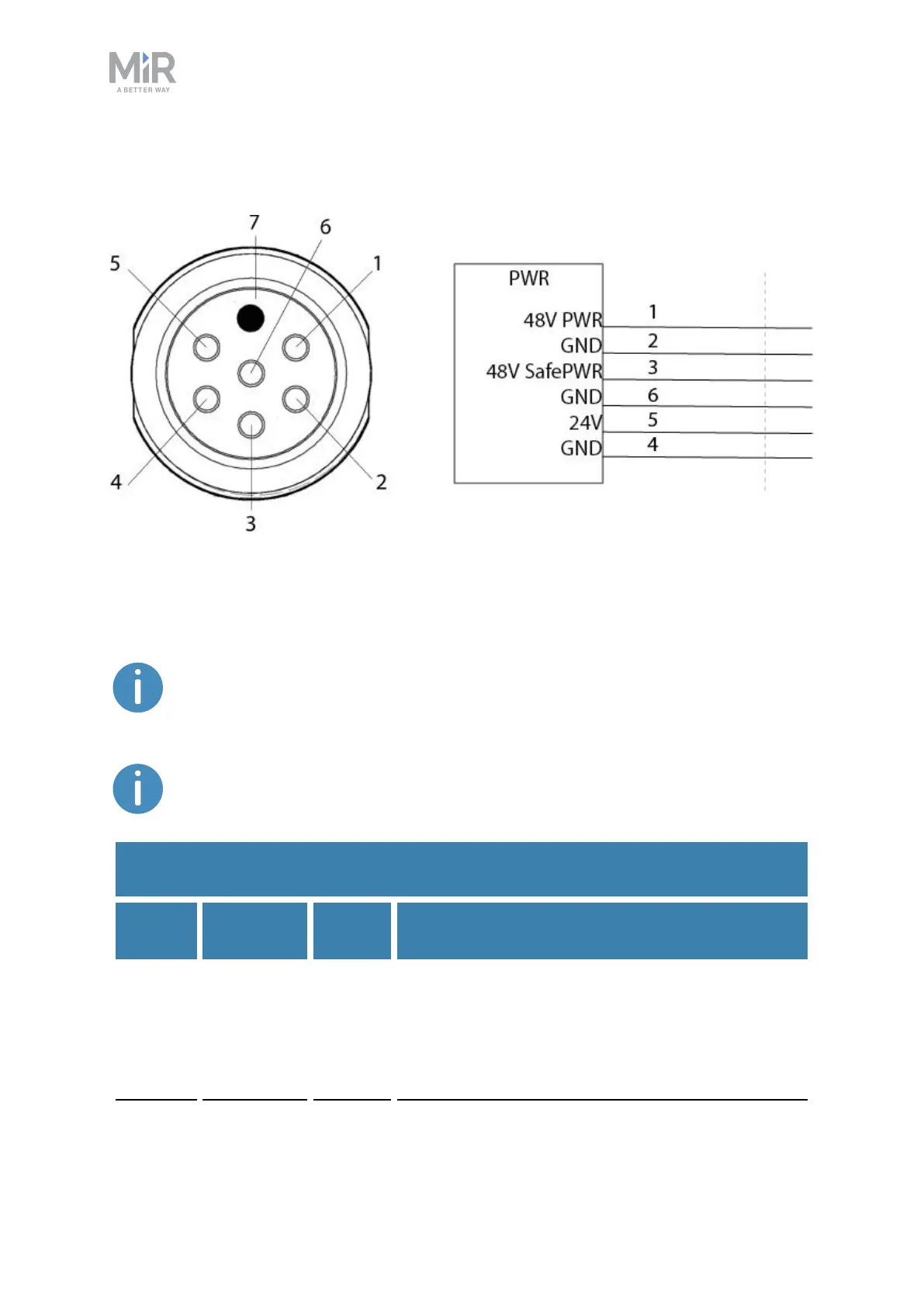
Figure 18.1. Pin numbers: female connector viewed from the front (left) and wiring diagram (right).
Table 18.1 contains the description of the pins of the Power interface.
The maximum current across pins 1 and 3 combined is 20 A. You cannot draw
20 Afrom both of them at the same time.
The voltage from pins 1 and 3 ranges between 41.8 - 53.8 V.
Pin
number
Signal
name
Max.
current
Description
1 48V PWR 20 A Turns off in case of a Protective or Emergency stop
via a transistor in the power board.
There are no additional safety precautions taken
with this power output. For this reason, it is
recommended to use the power output from pin 3
Table 18.1.
Description of the pins in the Power interface