8. Safety system
MiR200 User Guide (en) 10/2020 - v.3.1 ©Copyright 2017-2020: Mobile Industrial Robots A/S. 81
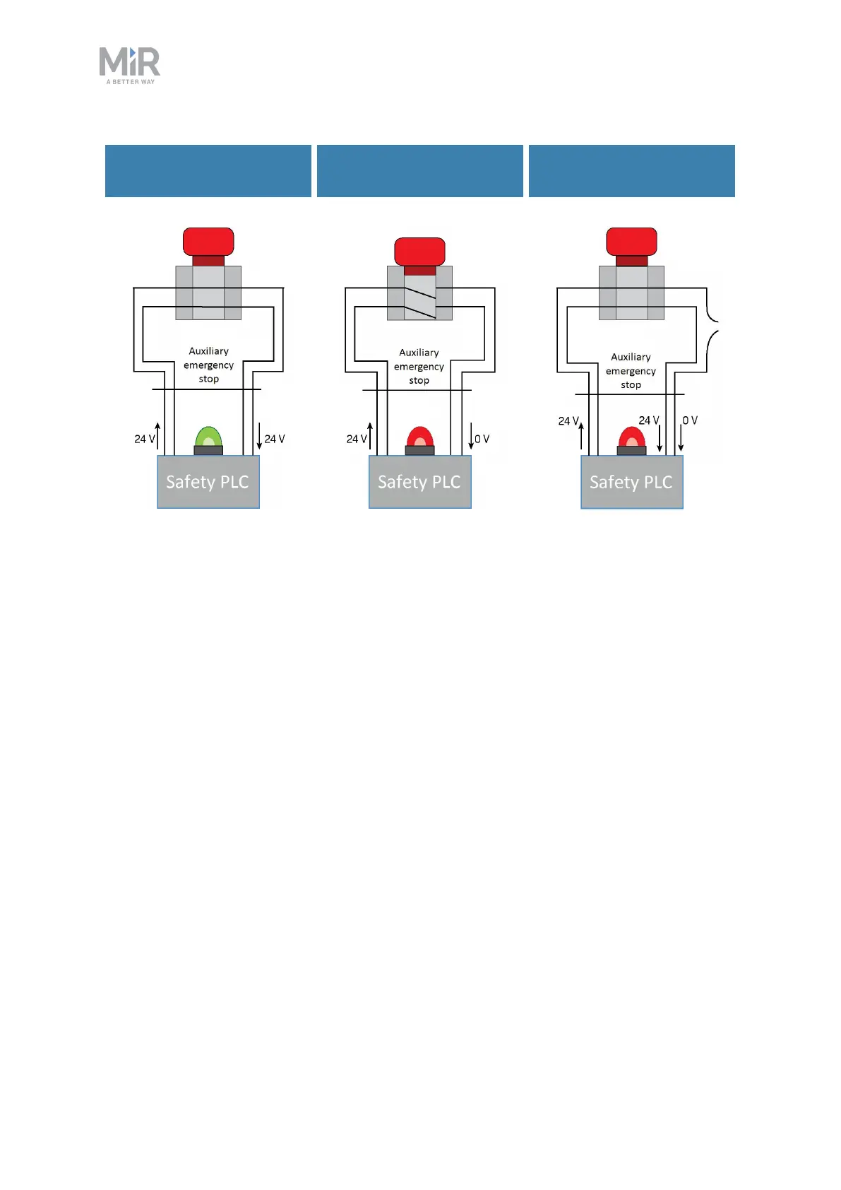
Emergency stop button
released
Emergency stop button
pushed
Emergency stop circuit
faulty
Figure 8.5. If the input pins deliver 24 V to the robot, it can operate. When you push a connected Emergency
stop button, both pins deliver 0 V, and the robot enters Emergency stop. If the pins do not deliver the same
input, the robot enters Protective stop until the circuits are fixed.
8.6 Robot computer
The robot computer is connected to the safety PLCvia an Ethernet cable. The safety PLC
sends all of the statuses of its various inputs to the robot computer so the information can be
sent to the robot interface. This enables you to identify which part of the safety system may
be causing a Protective or Emergency stop.
Additionally, the robot computer sends the current robot state to the power MiR board,
which regulates the status lights making them indicate which state the robot is in.