11
System Components
2.0 System Components
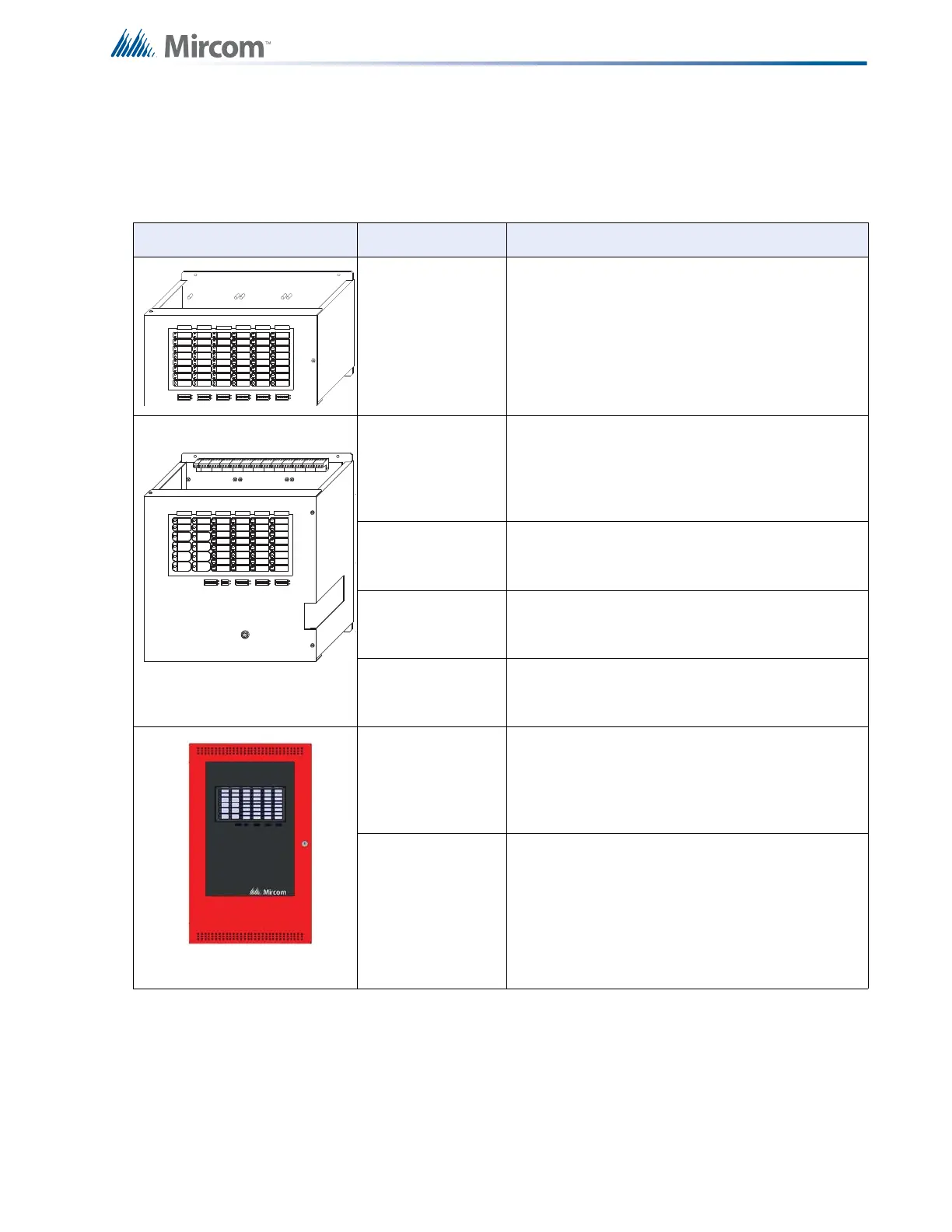
2.1 Chassis
Model Description
ECH-1048 48 zone extension chassis.
MCC-1024-6
(add suffix S for
slide switch
model)
Main Chassis with eight Style B / four Style D
initiating circuits, four Style Y or Z indicating
circuits, and a six ampere power supply. For more
information see 13.0 Appendix C:
Specifications on page 75.
MCC-1024-12
Same as MCC-1024-6, but with a 12 ampere
power supply. For more information see 13.0
Appendix C: Specifications on page 75.
MCC-1024-6S
Same as MCC-1024-6, but with disconnect slide
switches instead of DIP switches. For the U.S.A.
Market only.
MCC-1024-12S
Same as MCC-1024-12, but with disconnect slide
switches instead of DIP switches. For the U.S.A.
Market only.
MCC-1024-6ADS
Main Chassis with eight Style B / four Style D
initiating circuits, four Style Y or Z indicating
circuits, and a six ampere power supply. For more
information see 13.0 Appendix C:
Specifications on page 75.
MCC-1024-12ADS
Same as MCC-1024-6ADS, but with a 12 ampere
power supply. For more information see 13.0
Appendix C: Specifications on page 75.
DISCONNECT
ZONECONFIG.
ALARM
1
SILENCE
CIRCUIT
BREAKER
A.C. LINE
DET. ZONE
DISCONNECT
SIG. ZONE
DISCONNECT
8141
DISCONNECT
ZONE
8181
DISCONNECT
AUXILIARY
AUTOMATIC
ALARM SIGNAL
CANCEL
GENERAL
FIRE
DRILL
ALM/SUP/
TBL/BLDG
AUDIBLE SIL
SIGNAL
TEST/CONFIG
FAILURE
RESET
SYSTEM
MODE
REMOTE
A.C. ON
LAMP
TEST
TROUBLE
COMMON
FAULT
SUPERVISORY
COMMON
BATTERY
TROUBLE
GROUND
COMMON
ALARM
8
 Loading...


