43
Field Wiring
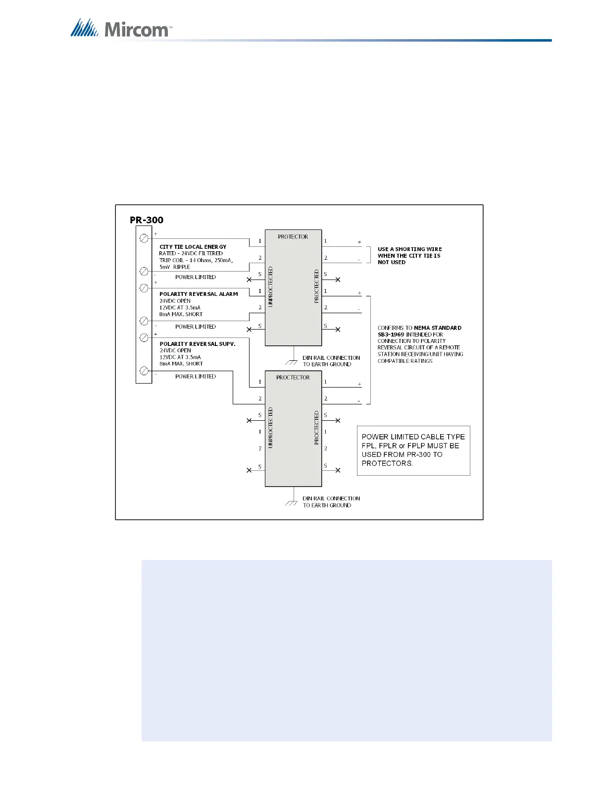
6.6 PR-300 Polarity Reversal and City Tie Module Terminal
Connections
Wire as shown below in Figure 24 using proper wire gauges. For more information see
Appendix C: Specifications on page 75.
For use in the U.S.A., the installer must add an Atlantic Scientific (Tel. 407-725-8000) Model
#24544 Protective Device, or similar UL-Listed QVRG Secondary Protector, as shown. For
use in Canada, the protective device is still recommended, but the PR-300 may be connected
directly to polarity reversal or city tie wiring.
Figure 24 Polarity Reversal and City Tie Module Terminal Connections
• Plug PR-300 ribbon cable (P1) into connector (P2) of the main fire alarm
module.
• Cut jumper (JW1) on the PR-300 module in order to transmit a trouble condition
to the monitoring station.
• Remove jumper plug from jumper JW4 on the main fire alarm module.
• The polarity reversal interface is power limited and must use type FPL, FPLR,
or FPLP power limited cable.
• For polarity reversal operation, short tie the city tie connection.
• Either the PR-300's city tie or polarity reversal interface may be used, but not
both.
• The city tie interface is not power limited.
• The terminal blocks are "depluggable" for ease of wiring.
Cable Resistance
Less than or equal to
3000 ohms

 Loading...


