28
Module Settings
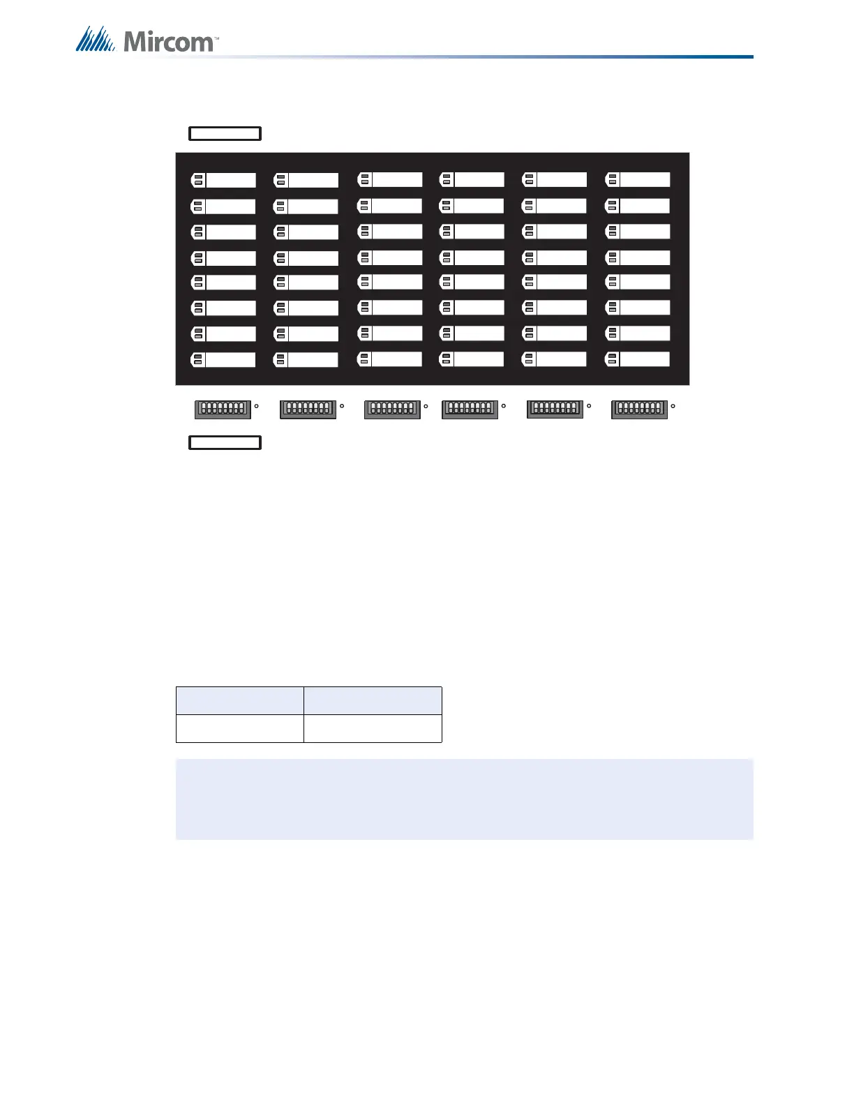
5.3 Adder Display Module
Figure 12 Adder Display Module (Part of Expander Chassis)
5.3.1 Connectors
The adder display module provides the following general purpose display points:
P1 Cable connects to P2 of main display module.
P2 Not used.
SW1 to
SW6
See 9.0 System Configuration on page 60 and 8.0 Indicators, Controls, and
Operation on page 49.
Chassis Type Display Points
ECH-1048
48
Note: The adder display module comes with a label sheet (NP-681) with blank slide-in
labels. This sheet may be run through a laser printer for labelling purposes before
being installed.
1 2 3 4 5 6 7 8
1 2 3 4 5 6 7 8
1 2 3 4 5 6 7 8
18
CIRCUIT
DISCONNECT
81
18
CIRCUIT
DISCONNECT
CIRCUIT
DISCONNECT
1 2 3 4 5 6 7 8
1 2 3 4 5 6 7 8
1 2 3 4 5 6 7 8
18
CIRCUIT
DISCONNECT
CIRCUIT
DISCONNECT
81
18
CIRCUIT
DISCONNECT
P1
P2
Zone 25
Zone 26
Zone 27
Zone 28
Zone 29
Zone 30
Zone 31
Zone 32
Zone 33
Zone 34
Zone 35
Zone 36
Zone 37
Zone 38
Zone 39
Zone 40
Zone 41
Zone 42
Zone 43
Zone 44
Zone 45
Zone 46
Zone 47
Zone 48
Zone 49
Zone 50
Zone 51
Zone 52
Zone 53
Zone 54
Zone 55
Zone 56
Zone 57
Zone 58
Zone 59
Zone 60
Zone 61
Zone 62
Zone 63
Zone 64
Zone 65
Zone 66
Zone 67
Zone 68
Zone 69
Zone 70
Zone 71
Zone 72