42
Field Wiring
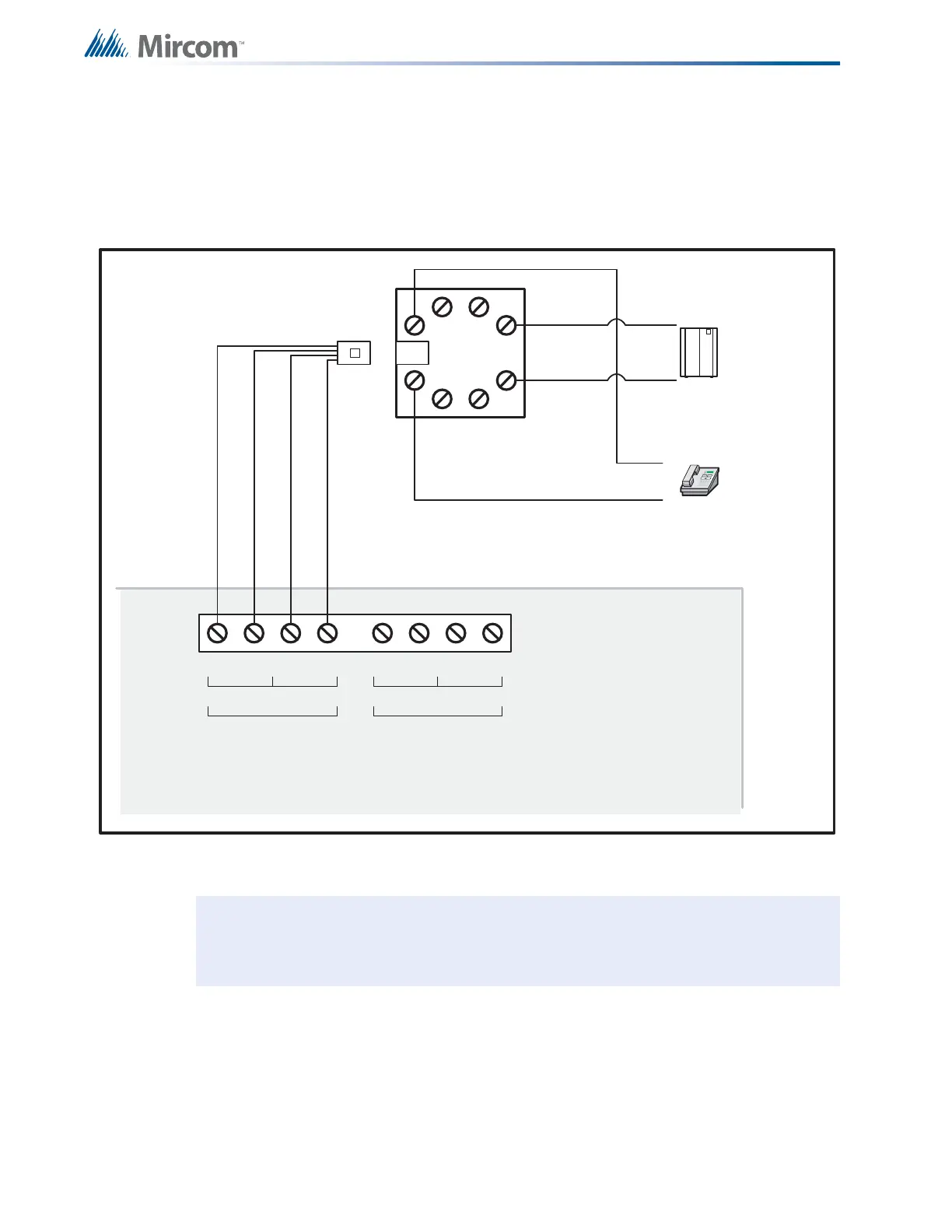
6.5 UDACT-300A Main Board Terminal Connections
Wire the two telephone line devices to terminals as shown below in Figure 23 below.
The UDACT-300A terminals are located on the top left hand corner of the board. If using a
cellular or wireless service, use the Line 2 interface connection only.
Figure 23 UDACT-300A Terminal Connections
Note: Most AHJ's do not allow the connection of premises telephones. See UDACT-
300A Instruction and Operation Manual (LT-888) for further details.
TTRR
premise telephone
IF permitted
TTRR
LINE-1 LINE-2
1
23
4
8
5
76
Public switch
Telephone company
wiring
TIP
RING
TIP
RING
RJ31X
RED
GREEN
GREY
BROWN
RES RESC.O. C.O.
Line 2 is Wired as shown for Line 1
UDACT-300A

 Loading...


