61
System Configuration
9.1.1 Three buttons and LED indicators are used in configuration mode
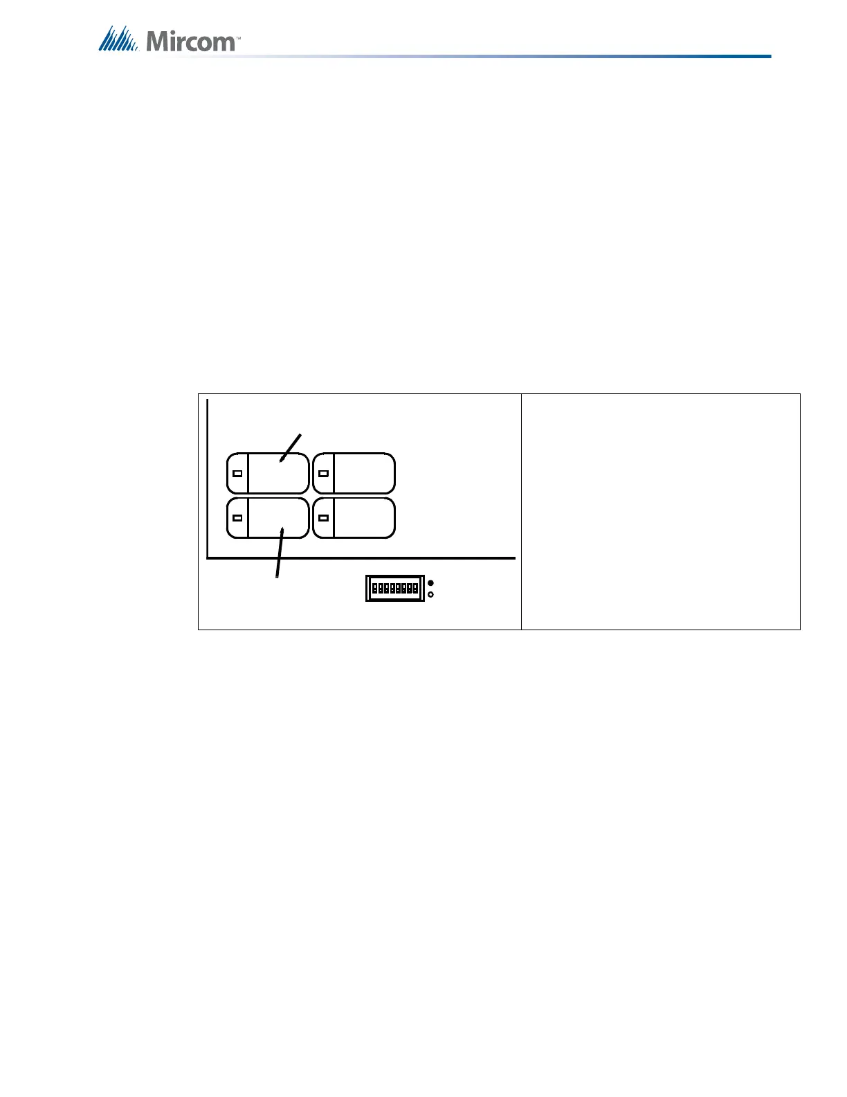
Figure 29 Configuration Indicators and Controls
Automatic
Alarm Signal
Cancel (yellow
button)
This becomes a "Select Setting" button and the LED indicator may
show the current status of a function.
General Alarm
(red button)
This becomes a "Confirmation" button for some functions, used
together with the Yellow Button.
Alm/Sup/Tbl/
Bldg Audible Sil
(blue button)
This button performs its normal function of silencing the buzzer.
California Code All other buttons are non-functional during configuration mode.
Additionally, the Green Power “ON” LED will be “OFF” during
configuration mode. Common trouble LED will flash to test. Config
LED (amber) will be on.
Figure 29 shows the positions of the
configuration DIP switch and the yellow
and red buttons. Each has a matching LED
indicator of the same color. Note that the
label Automatic Alarm Signal Cancel will
only be shown in an FA-1000 configured as
a two-stage system.
Configuration functions are selected by the
configuration DIP switches as follows in
Table 12 on the next page. Note that a
switch position of "0" is "OFF" (bottom
position) and "1" is "ON" (top position).
1 8
RED BUTTON
& RED LED
GENERAL
ALARM
ALM/SUP/TBL/
BLDG AUDIBLE
SIL
SIGNAL
SILENCE
CONFIG.
AUTOMATIC
ALARM SIGNAL
CANCEL
YELLOW BUTTON
& YELLOW LED

 Loading...


