20
Mechanical Installation and Dimensions
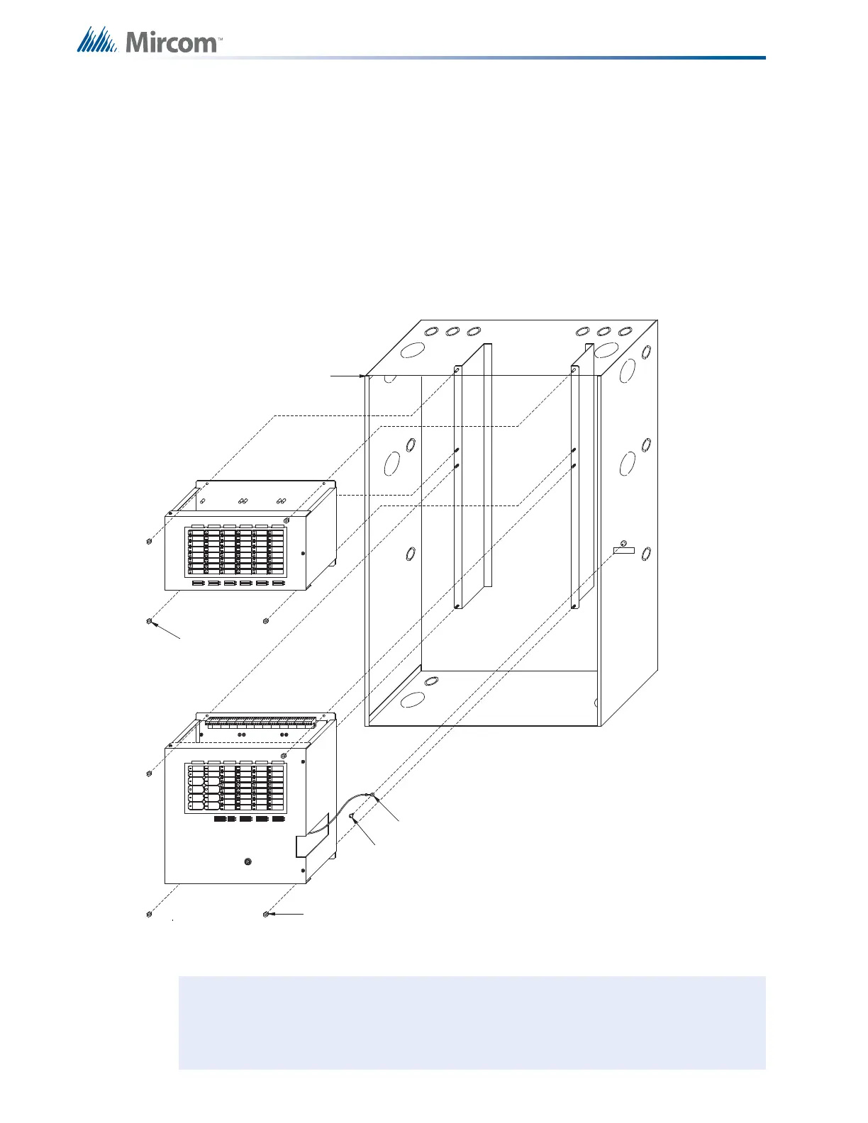
3.5 Main and Expander Chassis Installation
To install the expander chassis
1. Install the main and expander chassis into the BB-1072 enclosure, as shown in Figure 5,
using the supplied hex-nuts.
2. Group the incoming wires through the top of the enclosure to prepare them for wiring the
modules. Do not run the wires in-between the modules since this could cause a short
circuit.
3. Use a wire tie to group wires for easy identification and neatness.
Figure 5 Expander Chassis Installation
Note: Be sure to connect a solid earth ground (from building system ground / to a cold
water pipe) to the chassis earth ground mounting lug, and to connect the earth
ground wire lugs from both the main chassis and the expander chassis to the
ground screw on the backbox.
MAIN CHASSIS
EARTH GROUND LUG
BACKBOX
#8-32 HEXNUTS (4X)
#8 x 1/4" TYPE `B' SCREW
1 814181818
EXPANDER CHASSIS
#8-32 HEXNUTS (4X)

 Loading...


