45
Field Wiring
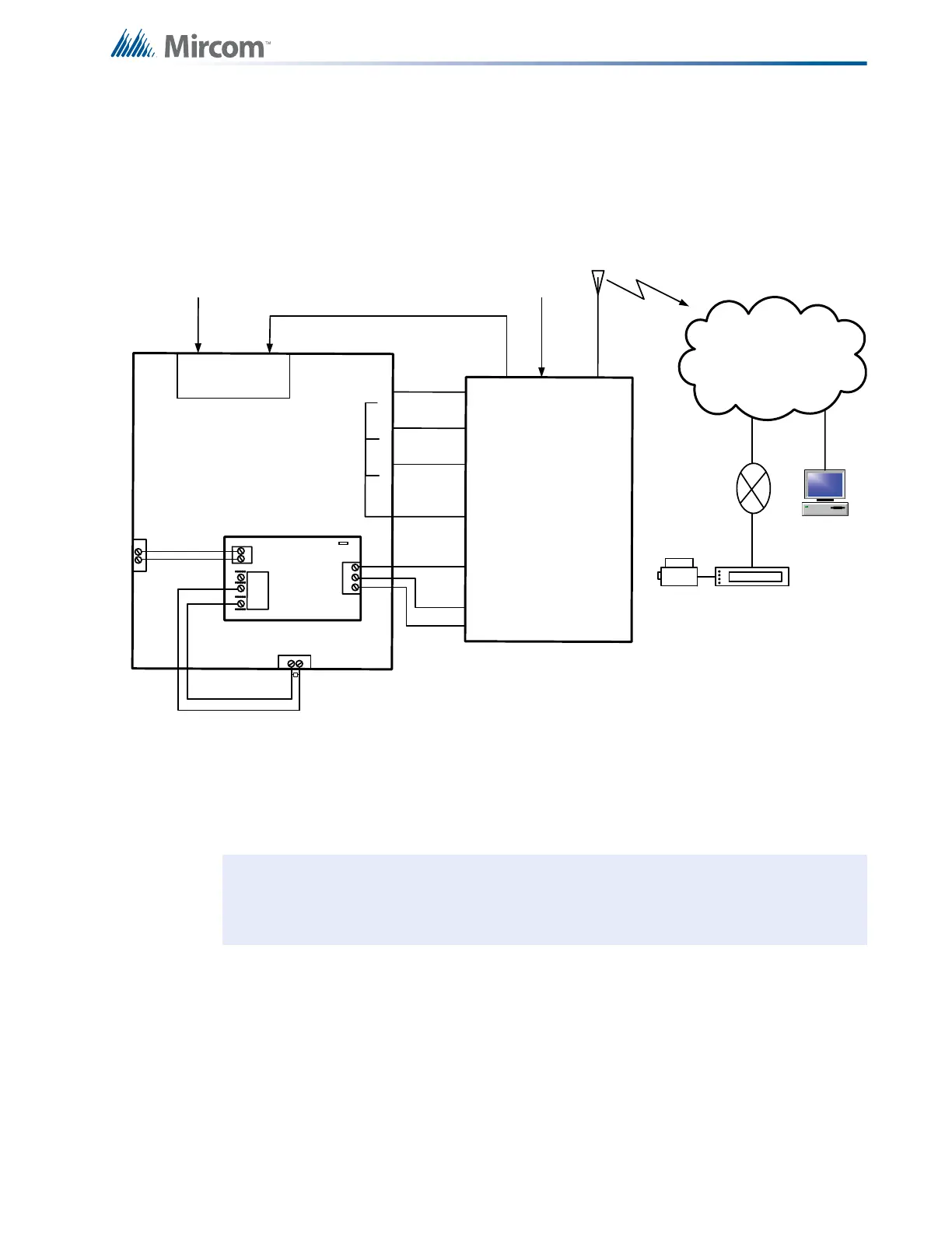
6.8 Connecting to a DCS SurGuard Receiver
A typical connection is shown in Figure 26. For information on Compatible DACR Receivers
see 11.0 Appendix A: Compatible Receivers on page 73.
Figure 26 Connecting an FA-1000 FACP to a DCS Surguard System Receiver
Note: The DSC interface is required if the installation requires S559 certification. If
S559 certification is not required, i.e. only local operation of the fire alarm panel,
this DSC interface is not required.
A
L
A
R
M
R
E
L
A
Y
S
P
V
R
E
L
A
Y
T
R
B
L
R
E
L
A
Y
R
i
n
g
T
i
p
Telephone
Line A
Connection
G
S
3
0
7
0
G
S
3
0
7
0
T
R
B
L
1
2
V
E
O
L
-
A
l
l
u
n
it
s
m
u
s
t
b
e
i
n
s
t
a
l
le
d
in
t
h
e
s
a
m
e
ro
o
m
.
-
A
ll
e
x
t
e
n
d
e
d
w
i
r
in
g
m
u
s
t
b
e
i
n
c
o
n
d
u
i
t
.
-
D
is
ta
n
c
e
m
a
x
1
8
meters
-
R
e
p
r
o
g
r
a
m
m
e
s
s
a
g
e
s
fr
o
m
G
S
3
0
7
0
Z
1
,
Z
2
,
a
n
d
Z
3
To GSM/GPRS
T
yp
i
c
a
l
In
s
t
a
ll
a
t
i
o
n
in
C
a
n
a
d
a
Line 2
Ring
Tip
Line 1
Ring
Tip
PCS-100
P
O
W
E
R
2
4
V
G
N
D
P
G
M
4
G
N
D
1
4
V
N
C
C
O
M
N
O
T
B
L
R
E
L
A
Y
J
W
1
1
0
P
G
M
4
AUX SUPPLY
+
-
+
-
Internet
Computer
Printer
SUR-GARD
SYSTEM IV
Internal IP: X.X.X.X
External IP: X.X.X.X
SG-Systems
Console 2.1
Default Gateway: X.X.X.X
Sub-Net Mask:X.X.X.X
Port #: YYYY (UDP)
Router
F
A
-
10
0
0
–
G
S
3
0
7
0
C
o
n
n
e
c
t
i
o
n
–
T
y
p
i
c
a
l
D
i
a
g
r
a
m
N
O
C
N
O
C
N
O
C
1
4
C
O
M
1
7
Z
3
1
6
Z
2
1
5
Z
1
T
1
R
1
Telephone
Line B
Connection
2
0
(
-
)
1
9
(
+
)
Trouble Zone Input
FA-1000

 Loading...


