22
Module Mounting Locations
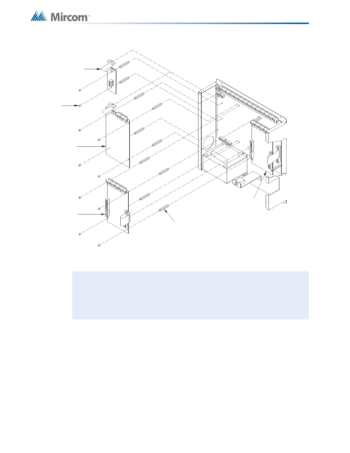
4.1 BB-1024 and BB-1072 Main Chassis Mounting Locations
Figure 6 BB-1024 and BB-1072 Main Chassis Mounting Locations
To Install Circuit adder modules
1. Install circuit adder modules from right to left using the supplied stand-offs (Figure 8 on
page 24).
2. Plug the first module with its 26-pin ribbon cable into P5 on the main fire alarm module
using the included MD-579 four-wire power cable (as described in 5.0 Module
Settings on page 25).
3. You can connect a second circuit adder module by plugging its 26 pin cable into the
matching socket on the module to its right, and by installing the supplied MD-579 four-
wire power cable (as described in 5.0 Module Settings on page 25).
Notes: Front plate is not shown. Other circuit adder modules may be:
• DM-1008A Detection Circuit Module
• SGM-1004A Signal Circuit Module
• RM-1008A Relay Circuit Module
PR-300 city tie
module (see
Notes below)
UDACT-300A
Dialer Module
(see Notes below)
#6-32 x 1
1
/
2
” M/F hex
spacer
Other Circuit Adder
Module
#6-32 x
1
1
/
4
” screw
Other Circuit
Adder