30
Module Settings
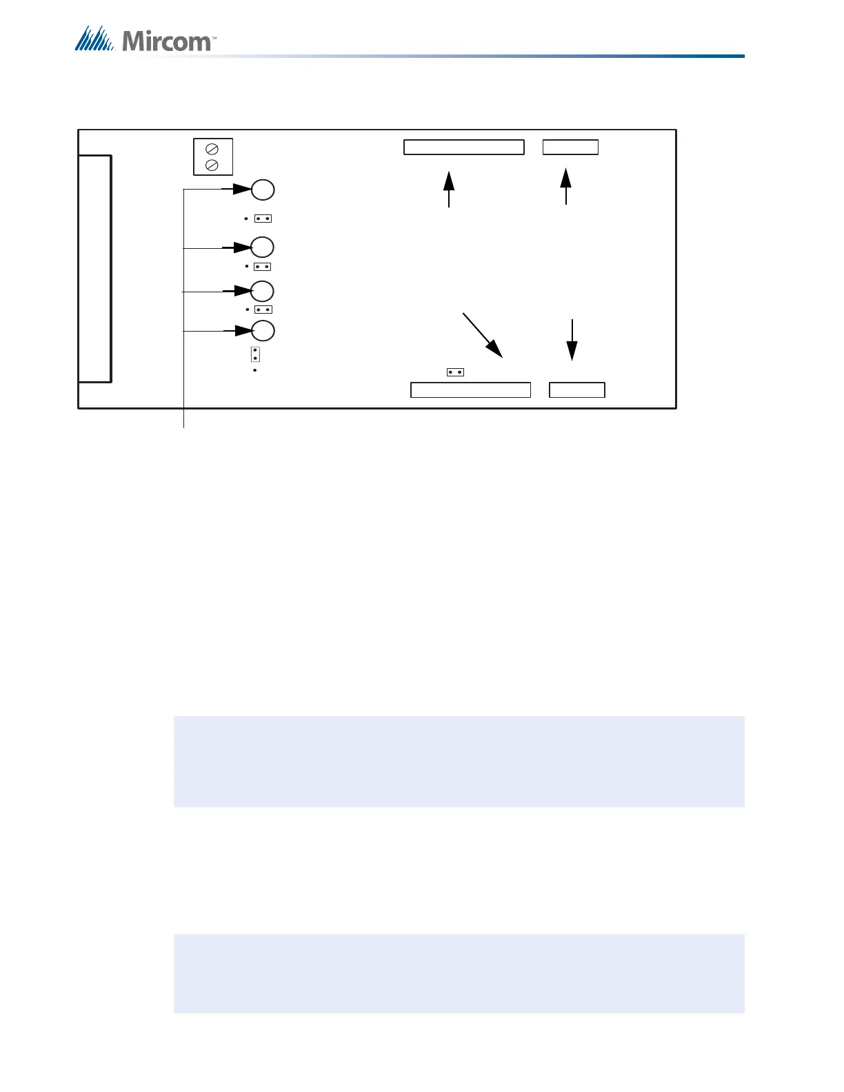
5.5 SGM-1004A Signal Adder Module
Figure 14 Signal Adder Module (Model SGM-1004A)
5.5.1 Jumpers
5.5.2 Components
There are four green LEDs on the board, one for each signal zone. A green LED will illuminate
or flash following the signal rate sent to its zone. It will be off when the system is normal and it
will illuminate when a signal zone is activated. The LED does not reflect what is happening on
the signal zone, just that it is receiving data to activate that signal zone.
JW1 Remove continuity jumper if there are any more adder modules installed.
JW2 Jumper pins for bell cut on Zone 1.
JW3 Jumper pins for bell cut on Zone 2.
JW4 Jumper pins for bell cut or on Zone 3.
JW5 Jumper pins for bell cut or on Zone 4.
JW11 Wire these terminals to a bell cut relay (for details see QRM-1001 Bell Cut
Module Installation and Operating Instructions, LT-666).
Notes: Jumper JW6 on the main fire alarm module must be removed if there are any
adder modules installed.
The SGM-1004A requires 4 display points.
Note: Jumpers JW2, JW3, JW4 and JW5 are positioned on pins 2 and 3 (right two pins
with board orientation as shown above) from factory.
P1
P3
P4
FIELD WIRING TERMINALS
P2
JW1
JW5
JW4
JW3
JW2
J11
1 2 3
GREEN SIGNAL LEDs
ZONE 4
ZONE 3
ZONE 2
ZONE 1
Data cable to P5 of main
fire alarm module or to
previous adder module
Data connector for next
adder module
Power connector to
P6 of main fire alarm
module or to previous
adder module
Power connector for
next adder module