19
Mechanical Installation and Dimensions
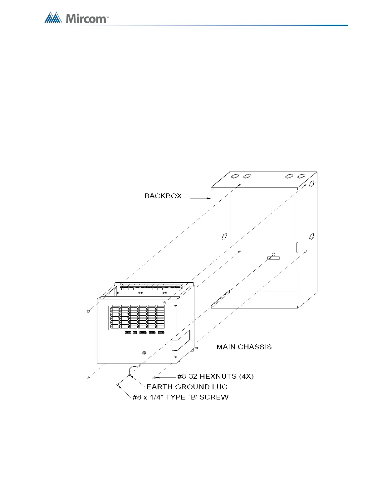
3.4 Main Chassis Installation
To install the main chassis
1. Install the main chassis in the BB-1024 backbox as shown in Figure 4 below, using the
supplied hex-nuts.
2. Group the incoming wires through the top of the enclosure to prepare them for wiring the
modules. Do not run the wires in-between the modules since this could cause a short
circuit.
3. Use a wire tie to group wires for easy identification and neatness.
4. Be sure to connect a solid earth ground (from building system ground / to a cold water
pipe) to the chassis earth ground mounting lug, and to connect the earth ground wire
lugs from the main chassis to the ground screw on the backbox.
Figure 4 Main Chassis Installation

 Loading...


